



- Tighten the handbrake and loosen the wheel nuts. Also loosen the drive shaft nuts using the appropriate wrench head as shown in figure 7, without turning them away.
- Place the front of the vehicle on stands so that the front wheels can turn freely.
- Disconnect the wires from the battery and remove the battery.
- Drain the coolant from the cooling system. To do this, unscrew the plugs on the cylinder block and on the radiator. The location of the plug on the cylinder block is shown in Figure 323. If the coolant is not yet old, drain it into a clean container. The coolant contains antifreeze and can be reused if it has not been in the cooling system for a long time. Otherwise, the disposal of the coolant is carried out in compliance with environmental protection regulations.
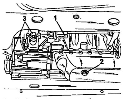
Figure 323. Bottom view of the engine and gearbox with location of drain plugs. 1. Plug on the cylinder block; 2. Engine oil drain plug; 3. Transmission oil drain plug
- Drain the oil from the gearbox and axle reducer. The location of both plugs (3), which must be unscrewed to drain the oil from the gearbox, is shown in Figure 323. The oil is drained into a clean container. The oil is drained from the engine if work on the engine is planned that requires draining the engine oil from the engine. To do this, unscrew plug 92) in Figure 323. After draining the oil, immediately tighten the plugs.
- Remove the large air distribution box in the middle of the engine compartment. Disconnect from the air filter and then remove the air filter assembly. On a turbodiesel engine, the charge air cooler is located in this location and must be removed in this case. Figure 324 shows the location of individual parts on a diesel engine. Disconnect the large hose near the air filter. There is a relay box located next to the battery. Disconnect all connected electrical wires and move them to the side.
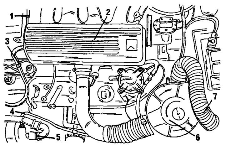
Figure 324. Diesel engine. 1. Connecting the fuel line; 2. Air distribution box; 3. Fuel hose; 4. Vacuum hose; 5. Connecting hose; 6. Air filter; 7. Air hose
- Remove the fuel heating device. It is located on the right side when viewed from the front, just in front of the relay box.
- Remove the battery tray.
- Raise the front of the vehicle and place it on secure stands.
- If there is an ABS system, it is necessary to remove the control unit. To do this, unscrew the two bolts from the bracket, disconnect the wires and remove the device.
- Disconnect the hoses from the heater fittings. The hoses have special fastening locks. There are small levers on both hoses. They should be turned to the right and the hoses pulled out. The locations of the hose disconnections are shown in Figure 325.
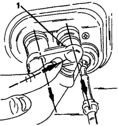
Figure 325. Disconnecting the heater hoses is performed using operations (1) and (2).
- To remove the power unit, it is necessary to set the engine compartment hood in a vertical position. Since a special tool is required to hold the hood in this position, it is best to unscrew the hood and set it aside in a safe place. To do this, mark the contours of the hinges on the hood with a pencil and unscrew the hinge bolts. While unscrewing the last bolt, have an assistant hold the hood.
- Disconnect the water hoses from the top of the radiator and from the bottom of the radiator. To do this, turn the hoses a quarter turn to the right and then remove them. The water hoses should also be released from the mounting clamps.
- Disconnect the throttle control cable. For more details on this, see:. chapter "Diesel engine fuel injection device".
- Disconnect the fuel inlet and outlet hoses. One hose is visible at (1) in Figure 324 and the second hose (2), connected to the hand pump, is disconnected from the pump.
- On the right side, near the radiator cap, disconnect the power steering pump hose. To prevent liquid from leaking, clamp the hose with a clamp. Also disconnect the vacuum hose from the pump. The location of the named parts is shown in Figure 326. Unscrew the bolt (2).
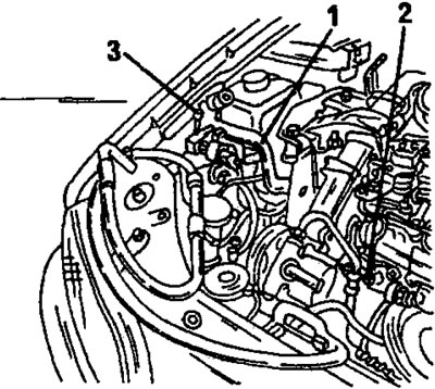
Figure 326. Disconnecting the hoses from the power steering pump. Clamp the hose (1) with a clamp (3). Loosen the bolt (2).
- Unscrew the muffler pipe from the exhaust manifold. To do this, unscrew the two nuts with cups from the bottom side and pull out the springs. Disconnect the connection. To ensure a tight connection, when the nuts are tightened to the required tightening torque, the springs are compressed. There are three gear shift rods located near the muffler (Figure 327). They should be pressed away from the levers by inserting a screwdriver behind the ball joints.
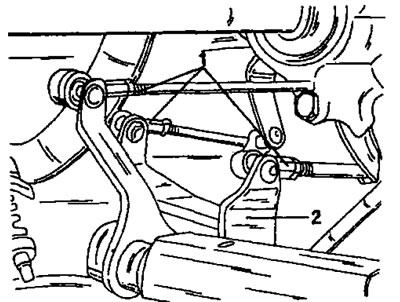
Figure 327. The gear shift rods (1) are connected to the levers (2) by ball joints.
- Remove the parts shown in Figure 328 from under the vehicle. These are the bolts (1), the protective cover (2) and two nuts (3).
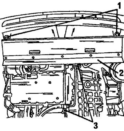
Figure 328. Bottom view of the car. The specified parts must be removed. 1. Bolts; 2. Protective cover; 3. Nuts
- Remove the shield from the wheel arch.
- After unscrewing the two nuts shown in Figure 329, loosen the moment support and move it to the side. Loosen both locknuts and turn the bolts half a turn to release their heads from the retainers.
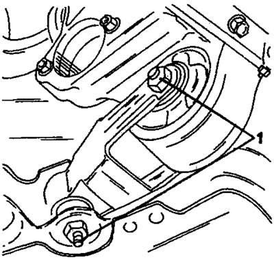
Figure 329. Fastening the moment support. Unscrew the nuts (1) on both sides.
- Unscrew the radiator mounting bolts from the top side, remove the fasteners and carefully pull out the radiator.
- Now place the front of the car on stands and remove the wheels.
- You press the right and left ball joints from the steering knuckles as described in the section "Front wheel suspension". The connection between the steering knuckle and the ball joint journal is secured with a tie bolt.
- Remove both drive shafts in accordance with the instructions in the relevant section.
- Disconnect the speedometer flexible shaft.
- Disconnect the electrical wires from the gearbox (for example, the starter wire and the reverse light switch wire).
- Disconnect the vacuum hose from the brake booster.
- Attach the power unit to a crane or other suitable lifting device using chains or cables and slowly pull the power unit until the chains or cables are taut.
- Remove the right engine mount. On a turbodiesel engine, it has a stop inserted into it, which must be removed to provide access to the mounting nut. Remove the carrier bracket completely.
- On the opposite side of the engine, disconnect the clutch cable and unscrew the nut (2) in the middle of the suspension support (1) in Figure 330.
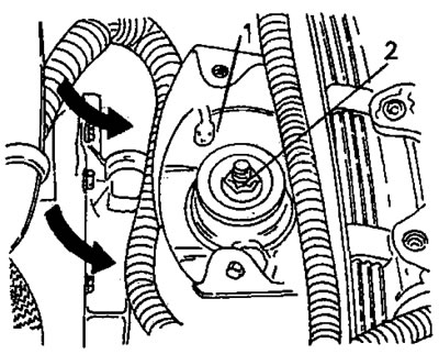
Figure 330. Fastening the suspension support from the gearbox side. The suspension bracket (1) is secured to the gearbox with a nut (2). The arrows indicate the location of the mounting bolts on the suspension console.
- Once again, make sure that all connections are made, lift the power unit and remove it from the engine compartment. At the same time, constantly ensure that tubes, hoses, wires, etc. do not get caught on the power unit and that all disconnections are made.
- After removal, place the engine on a suitable support, such as a wooden block, and secure the power unit against tipping over. After this, inspect the entire power unit for external damage and leaks, such as traces of oil, which may indicate damaged parts. After this, clean the outside of the engine. Cover all sensitive parts.