



Engine disassembly is described in detail below in the section titled "Repair and Overhaul." This section describes tasks that can be performed both with the engine removed and while it's still in the vehicle, eliminating the need to repeat descriptions of specific tasks associated with engine disassembly. If complete disassembly of the engine is required. you just need to combine individual work operations, and in the specified sequence.
In general, it is important to always remember to mark all moving parts before removal so that they can be reinstalled in the same position if they are to be reinstalled. This applies to all engines and is especially important for pistons, valves, bearing caps and bearing shells. Place the removed parts so as not to mix them up.
Under no circumstances should bearing and mating surfaces be marked with a drafting tool or even stamped with numbers on them. Paint is best for marking. The valves are best installed in the holes in the bottom of an inverted cardboard box, so that their numbers can be written next to them on the box. Figure 333 shows the location of the removed valves of an 8-valve engine.
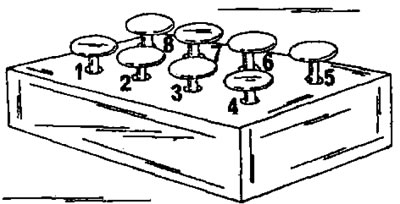
Figure 333. The valves can be installed in the holes in the bottom of an inverted cardboard box in the order of their subsequent installation.
- Most parts are made of aluminum and require handling accordingly. If hammer blows are required to separate individual parts, only a rubber, plastic or leather hammer should be used.
- If a prescribed mounting stand is not available, it is best to cut wooden blocks to size to allow the engine to be mounted on them with access to the top and bottom of the engine. After removal, the cylinder head can be secured in a vice using a metal bracket screwed to the intake manifold studs.
- Complete disassembly of the engine is carried out as follows:
- Drain the oil from the engine.
- Loosen the bolts connecting the engine to the gearbox and separate the gearbox from the engine, without placing the weight of the gearbox on the clutch shaft.
- Unscrew the oil filter from the side of the engine. In this case, use the chain wrench shown in Figure 334. The oil filter is located behind the alternator.
- Pull out the oil dipstick.
- Remove the leading and driven clutch discs. To lock the crankshaft when unscrewing the bolts, insert the locking device shown in Figure 335 or a screwdriver into the flywheel ring gear.

Figure 334. The oil filter is unscrewed using a chain wrench.
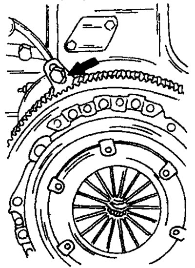
Figure 335. Holding the flywheel from turning. The blocking segment is inserted into the teeth of the flywheel ring gear.
- Remove the oil pan. To do this, place the engine on the cylinder block and unscrew the 23 bolts evenly in a circle. Remove the oil pan (Figure 336) and remove the gasket.
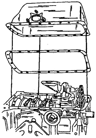
Figure 336. Removing the oil pan.
- While holding the flywheel from turning in the manner shown in Figure 335, loosen the crankshaft belt pulley bolt. Also unscrew the flywheel bolts. If the flywheel is stuck tight, tap it with a plastic hammer. There is no need to mark the flywheel installation position, as it can only be installed in one position.
- Remove the crankshaft belt pulley from the shaft using two pry bars. You can also use a puller, the two bolts of which can be screwed into the threads on the belt pulley.
- Unscrew and remove both timing belt covers from the front of the engine. Also remove the casing from the bottom side. Figure 337 shows the disassembly stage of this work operation.
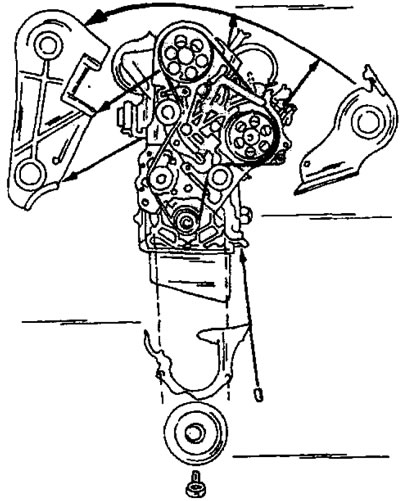
Figure 337. Parts removed from the front side of the engine.
- Prepare three M3 x 40 bolts. Insert one of the bolts into the camshaft pulley at location (1) in Figure 333, and insert the other two bolts into the high-pressure fuel pump drive pulley at locations (2) and (3). This will lock the valve timing mechanism. If a complete disassembly of the engine is required, this work is not performed. Bolts are inserted only if it is necessary to maintain the timing adjustment.
- Loosen the bolts (4) and (5) of the belt tensioner. Insert an extension with a 9.52 mm square into the square hole (b) in Figure 338, (and ratchet), as shown in Figure 339 to compress the springs of the automatic belt tensioner. This is a four-sided adapter from a set of key heads with a 3/8-inch drive. Re-tighten the bolt (5) in Figure 338 to hold the tensioner in the new position.
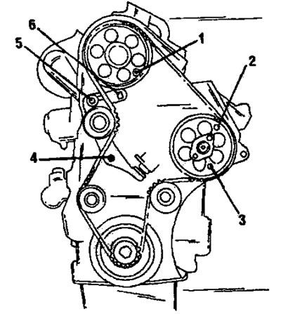
Figure 338. Removing and installing the timing belt 1. Inserted bolt; 2. Inserted bolt; 3. Inserted bolt; 4. Belt tensioner bolt; 5. Belt tensioner bolt; 6. Square hole
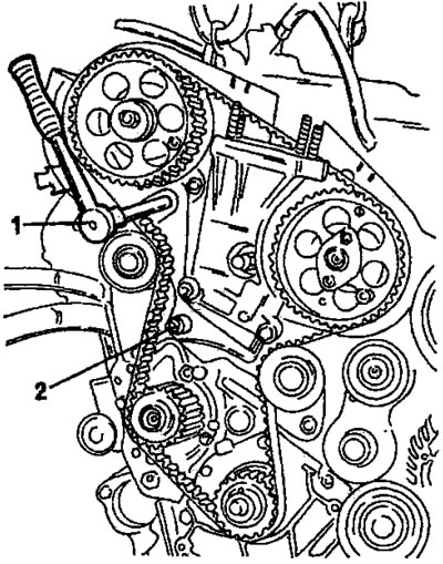
Figure 339. Crumpling of the toothed belt. Loosen the nut (2) and the ratchet nut and then turn the tensioner with the wrench head extension (1) to compress the springs.
- Carefully remove the timing belt forward from the timing pulleys.
- Remove the cylinder head as described in the relevant subsection.
- Loosen the five water pump mounting bolts and remove the water pump assembly. There is a gasket installed under the water pump.
- Unscrew the two thermostat housing bolts and remove the thermostat housing.
- Remove all parts from the outside of the engine. These include an oil cooler, vacuum pump, ventilation components, etc.
- Remove the toothed pulley from the crankshaft. This is done using two crowbars.
- After unscrewing bolts (2) and (3) in Figure 340, remove the tension roller (4). The spring is located on the inside of the engine support bracket. To hold the spring and pusher in their position, a special tool is used in the workshop. Therefore, when removing the staple, proceed with caution.
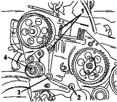
Figure 340. Remove the upper tension roller (4) after unscrewing bolts 1, 2 and 3.
- Unscrew the two bolts (1) in Figure 341 and remove the tension roller located in the middle.
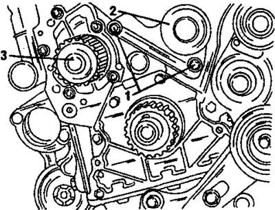
Figure 341. Remove the belt tension roller in the middle after unscrewing the bolts. 1. Bolts; 2. Tension roller; 3. Water pump
- Unscrew the cover in front of the oil pump (6 bolts) and remove the gasket. Carefully press out the flange, which is seated on two centering pins.
- From the bottom of the engine, unscrew the three oil pump mounting bolts. Pull the spacer plate to the side (Figure 342), disengage the drive chain from the oil pump sprocket and remove the oil pump. Figure 343 shows how to remove the oil pump while disconnecting the chain.
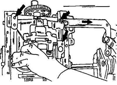
Figure 342. Removing the oil pump. Remove the spacer plate in the manner shown. The pump bolts are indicated by arrows.
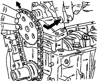
Figure 343. When removing the oil pump, pull the oil pump sprocket upwards. After this, the drive chain and sprocket are removed.
- Remove the oil pump drive sprocket and wedge from the crankshaft and then remove the chain.
- Remove the camshaft timing pulley. Also remove the high pressure fuel pump pulley. The parts to be removed are shown in Figure 344.
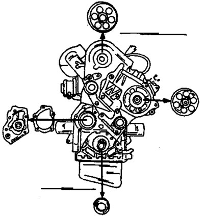
Figure 344. Parts removed from the front of the engine.
[Original can be viewed at: Peugeotbook.ru]
- Using Figure 345, remove the high pressure fuel pump and fuel injection lines.
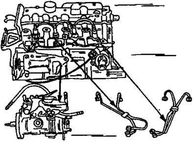
Figure 345. Removing the high-pressure fuel pump and fuel injection pipes.
- Loosen the nuts securing the connecting rod bearing caps, remove the bearing caps and pistons together with the connecting rods and stack them in the order of installation.
- Remove the main bearing caps, having first marked the position of the caps in the engine crankcase. Place the bearing caps and shells in the order of installation.
- Remove the crankshaft oil seal from the flywheel side. The seal must be replaced.
- Remove the crankshaft and the upper halves of the bearing caps from the holes. Mark and also remove the half washers to adjust the axial clearance.
- The pistons and connecting rods are disassembled in accordance with the instructions of the relevant section. The piston pins are secured in the grooves in the piston bores by retaining rings.