



Engine disassembly will be described in detail further in the "Repair and Overhaul" section. This describes tasks that can be performed with the engine both removed and installed, eliminating the need to describe tasks related to specific disassemblies twice. If complete disassembly is required, individual work processes must be combined, and in the specified sequence.
In principle, when disassembling, all moving and movable parts should be marked before removal to ensure their installation in their original position. This is especially important for pistons, valves, bearing caps and bearing shells and applies to all engines. The parts must be folded to avoid confusion during installation.
Under no circumstances should bearing and sealing surfaces be marked with a drafting stamp or, even more so, with a digital stamp. Paint is best for marking parts. It is best to insert the valves into the bottom of an inverted cardboard box, and write their numbers on the box with poison. Figure 308 shows the placement of the valves in a cardboard box.
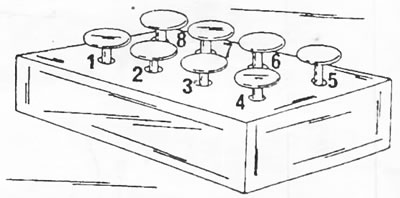
Figure 308. The valves can be inserted into the bottom of the inverted cardboard box in the order shown in which they are installed.
Many of the parts are made of aluminum and require handling accordingly. If hammer blows are required to separate certain parts, only a rubber, plastic or leather hammer should be used for this purpose,
If a dedicated mounting stand is not available, appropriate wooden blocks should be cut to provide access to the top and bottom of the engine mounted on them. After removal, the cylinder head can be clamped in a vice with a metal clamp to which the intake manifold pin bolts are screwed.
Complete disassembly of the engine is carried out as follows:
- Drain the oil from the engine. To do this, unscrew the drain plugs, the location of which is shown in Figure 309.
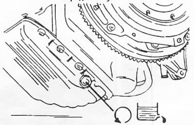
Figure 309. The oil drain plug is located on the bottom of the oil pan directly under the flywheel.
- Loosen the bolts connecting the gearbox to the engine and separate the gearbox from the engine, without placing the weight of the gearbox on the clutch shaft.
- Unscrew the oil filter from the side of the engine. To do this, use the special key shown in figure 221. The oil filter is located on the top side of the oil radiator. Unscrew the connecting sleeve and remove the oil radiator. It is also necessary to unscrew the filter base. The oil filter and oil cooler are shown in Figure 310. Remove the remaining parts shown in the figure as well. Depending on the engine design, the oil filter may be installed without an oil cooler.
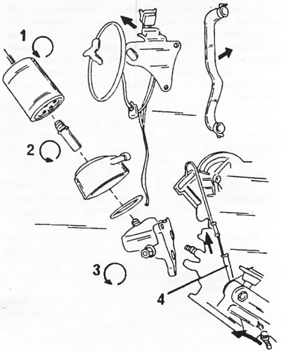
Figure 310. Location of the oil filter if there is an oil radiator. The remaining parts are also removed. The oil dipstick is located in close proximity. 1. Oil filter; 2. Connecting tube; 3. Oil filter base; 4. Oil dipstick
- Pull out the oil dipstick.
- Remove the leading and driven clutch discs. To lock the crankshaft when loosening the bolts, place the stopper shown in Figure 311 in the flywheel ring gear or hold the flywheel with a screwdriver inserted into the flywheel ring teeth.
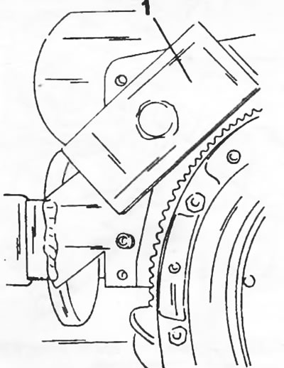
Figure 311. The flywheel ring gear is locked by a stopper (1).
- Unscrew the two nuts and remove the support (3) shown in Figure 312 and the gasket. Unscrew the eight nuts and remove the intake manifold.
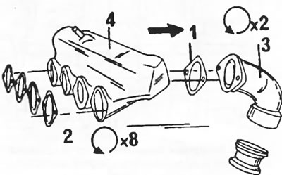
Figure 312. Removing the intake manifold. 1. Manifold nipple gasket; 2. Manifold gaskets; 3. Connection elbow; 4. Intake manifold
- Remove the turbocharger (see Figure 330). Unscrew the eight nuts and remove the exhaust manifold. Remove four gaskets. The gaskets must be replaced.
- Unscrew the plug from the middle part of the cylinder block on the oil filter side.
- Unscrew and remove the fitting with the connecting hose.
- Unscrew the eight nuts and remove the intake manifold from the cylinder head. Remove four gaskets. When assembling, the gaskets must be replaced.
- Unscrew the oil pipe from the top to the cylinder head.
- Unscrew the injection pipes from the high-pressure fuel pump and injector.
- Loosen the cylinder head cover fasteners and remove the cover. This stage of work is shown in Figure 313.
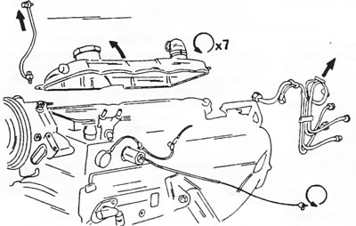
Figure 313. Remove the indicated parts from the cylinder head. Disassembly of the cylinder head is carried out later.
- Remove the two timing belt covers from the front of the engine.
- Loosen the fastening of the timing belt tension roller, press the roller to the side and remove the timing belt. In the same way, loosen the high pressure fuel pump belt roller and remove the belt. Both videos can be removed.
- Loosen the crankshaft pulley nut (with a 36 mm wrench) and remove the belt pulley from the crankshaft.
- Loosen all toothed pulleys one by one.
- Two of them are secured with three bolts and one with one nut. Figure 314 shows the arrangement of the toothed pulleys. The high pressure fuel pump toothed pulley must be removed using a special puller. After this, remove the oil pump and high pressure fuel pump.
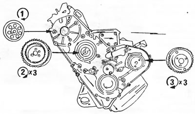
Figure 314. Location of toothed pulleys on the front side of the engine. Tightening torques are given below.1. 60 nm; 2. 35 nm; 3. 21 nm
- After removing the listed parts, unscrew the board from the front side of the engine.
- Unscrew the rocker arm shaft and pull out the valve push rods one by one. Place the push rods in the order they were installed or stick them into a piece of cardboard. Write the corresponding valve number in front of each push rod.
- In several passes, in the reverse order to that shown in Figure 315, loosen the cylinder head bolts and remove them.
[Text taken from the website: www.peugeotbook.ru]
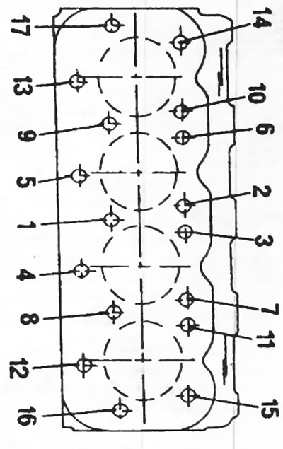
Figure 315. Cylinder head bolt tightening sequence. Unscrewing the bolts is done in reverse order.
- Remove the cylinder head and its gasket. A tightly seated cylinder head can be loosened with a few blows from a plastic or rubber hammer.
- Pull the tappets out of the cylinder block one by one. They should also be stacked in the order of installation.
- Unscrew the camshaft mounting plate and remove the shaft from the cylinder block.
- Remove the oil pan. To do this, place the engine on the surface of the cylinder block to drain the remaining oil. The oil pan is actually a plate attached to the lower part of the engine crankcase. It should be removed, as well as the oil receiver mesh. Figure 316 shows the removal of the specified parts.
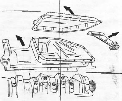
Figure 316. Removing parts from the bottom of the cylinder block.
- Holding the flywheel as shown in Fig. 311, unscrew the flywheel. If necessary, tap it with a plastic hammer. The flywheel does not need to be marked, since it can only be installed in one position.
- Loosen the nuts securing the connecting rod bearing caps, remove the bearing caps and remove and fold the pistons together with the connecting rods in the order of installation.
- Remove the main bearing caps, marking the relative positions of the caps in the engine crankcase on opposite sides. Place the bearing caps and liners in the order they were installed.
- Remove the crankshaft and take the upper halves of the bearing shells out of the holes. Also mark and remove the half washers to adjust the axial play of the crankshaft.
- Pistons and connecting rods can be disassembled in accordance with the instructions in the relevant section. The piston pins are held in place by retaining rings in the piston pin bore grooves. Store parts together.
- If necessary, remove the parts attached to the cylinder block, namely the oil dipstick guide tube, the cooling system circuit boards on the front and rear sides, and the lubrication channel plugs (be sure to replace the gaskets), as well as lubrication nozzles on the inside of the cylinder block.
- Disassembly of the oil pump is carried out in accordance with the instructions below.
- After disassembly, thoroughly clean all parts and assess their suitability for reinstallation in accordance with the instructions below.