



- Before assembly, it is necessary to check that all parts are clean and do not contain foreign objects.
- Apply a coat of motor oil to all moving or sliding parts. This should be done just before assembly, and not when the parts are already assembled, since otherwise the oil access to the direct support points may be blocked. It is especially important to provide ample lubrication before assembly. Pistons, piston rings and cylinder walls.
- Thoroughly clean all cylinder block parts if the engine has been completely disassembled. When partially disassembling the engine, do not allow foreign objects to enter the disassembled parts or cavities of the engine. To avoid this, all holes should be either sealed or covered with rags.
- It is best to blow out lubrication channels and holes with compressed air. If compressed air is not available, clean all channels and holes with a wooden stick, but under no circumstances with metal objects. When assembling, be sure to install new seals, gaskets, etc. Under no circumstances should you skimp on these parts or install obviously damaged ones.
- The table of sizes and adjustments shows the wear limits of the main moving parts. If in doubt or if the wear limit is approaching, it is better to replace the part, thereby saving on disassembling the engine in the near future.
- All spare parts should be purchased only from official dealerships, indicating the engine number. Since modernization and, consequently, changes in parts are constantly taking place, only your supplier can provide the necessary spare part.
- All removed boards and unscrewed plugs must be installed with new gaskets.
- Install four lubrication nozzles. Tighten the bolts to a torque of 23 Nm.
- Assemble pistons and connecting rods according to the instructions section 20.5.3.
- Insert the connecting rod bearing shells in accordance with the markings (when reinstalling the old parts). The guide projections of the liners must fit into the slots of the connecting rod holes.
— Insert the main bearing journals with the lubrication grooves into the holes. The guide tabs must fit into the recesses in the bearing holes. Also check that the centering bushings for the main bearing caps are inserted (two for each bearing). Figure 317 provides installation details.
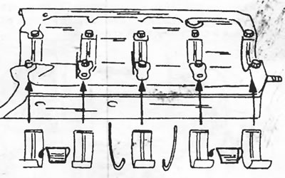
Figure 317. Bearing liners with lubrication grooves are installed in the engine crankcase.
Place both half washers on the middle bearing to adjust the axial play of the crankshaft. The oil grooves on both half washers must face outward. Lubricate the washers thoroughly with engine oil. Figure 318 shows the location of the washers. The thickness of washer "e1" on one side must be equal to the thickness of washer "e2" on the other side.
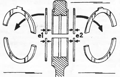
Figure 318. Half washers for adjusting the axial play of the crankshaft; are installed in the specified location. The thickness of washers "e1" and "e2" on both sides must be the same.
- Carefully insert the crankshaft into the bearing shells. The shaft journals must be well lubricated with engine oil. To do this, use an oiler and rub the oil in with your fingers. Do not use a brush to apply the oil.
- Install bearing caps with inserted liners (adjusting washers in the center bearing cap) in the same order (Figure 319). Install bearing caps in accordance with their numbering. Install the bearing cover on the flywheel side with a half-gasket. Cover the bottom side of this lid with sealing compound.
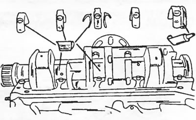
Figure 319. Installing main bearing shells. Cover the specified surfaces with a sealing compound.
After this, check the axial play of the crankshaft as follows:
- Mount the dial indicator on the appropriate stand at the front of the engine and place the measuring rod of the instrument on the surface of the crankshaft boss, as shown in Figure 235. If the dial indicator has a magnetic stand, you can place it on the shaft. and place the measuring probe against the smooth surface of the cylinder block.
- Press the crankshaft with a screwdriver on one side and set the indicator scale to zero.
- Press on the crankshaft from the other side and read the reading from the dial indicator scale. The measurement result should be between 0.045 and 0.16 mm.
- If the measurement result exceeds 0.32 mm, two larger half washers must be installed. Both washers must be the same thickness. In addition to washers with a nominal thickness of 2.30 mm, there are washers with thicknesses of 3.10, 3.14, 3.18, and 3.22 mm. To prevent crankshaft misalignment, it is important to install washers of the same thickness.
- Tighten the bolts of all bearing caps one by one, starting from the middle, to a tightening torque of 95 Nm.
Note: Check with your service station to see if the main bearing cap bolts can be reinstalled. Not all three car manufacturers share the same point of view.
- Screw two bolts into the crankshaft flange (flywheel bolts) and insert a screwdriver between the bolts. To check the free rotation of the crankshaft, turn it with a screwdriver. If the shaft jams, find out the cause before continuing with engine assembly.
- Lay out the assembled pistons and connecting rods in the installation order. Place a tension band on the first piston and insert it into the cylinder bore, which is well lubricated with engine oil (Figure 237). At the same time, start the connecting rod so that it sits on the crank pin. When reinstalling the old liners, do not mix up their installation locations. After installing the piston, check the position of its recess. Install the piston of the fourth cylinder in the same way.
- Insert the bearing shells into the bearing caps of both installed connecting rods in accordance with the markings. Lubricate the bearing surfaces thoroughly with motor oil. Re-installed liners are placed in the corresponding bearings. Tighten the caps to a torque of 90 Nm.
Note: In this case, you should also check with your service station to see if the connecting rod bearing cap bolts can be reinstalled.
- Turn the crankshaft until the other two journals are in the lower position and install the two remaining pistons in the described manner. After installation, check again to see if the crankshaft is jamming.
- Check again that the crank mechanism is correctly assembled and coat the well-cleaned contact surface of the lower part of the engine crankcase with sealing compound. Also apply a little sealing compound to the rubber gasket of the main bearing cap. Install the engine crankcase housing and tap it with a rubber hammer. Temporarily tighten the mounting bolts by hand.
- Place a new O-ring on the oil intake tube and screw the tube on.
- Lubricate the sealing lips of the new rear oil seal with engine oil, place the oil seal on the crankshaft and press it into the crankcase housing up to the edge. The arrow on the outside of the seal must point in the direction of engine rotation, that is, to the left, when viewed from the flywheel side.
- Press the new oil seal into the camshaft hole. For this purpose, you can use a pipe with an outer diameter of 35 mm.
- Generously lubricate the camshaft journals with engine oil and carefully push the shaft into the cylinder block. Place the retaining plate (3) shown in Figure 320 on the cylinder block and simultaneously insert it into the camshaft slot. Align the hole and insert the bolt. Tighten the bolt to a torque of 6 Nm.
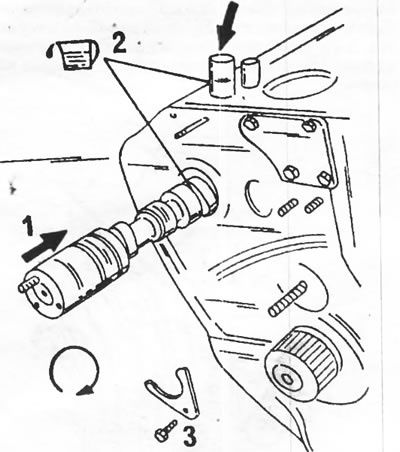
Figure 320. Installing the camshaft and tappets. 1. Camshaft; 2. Pusher; 3. Retaining plate and bolt (16 Nm)
- Check the axial play of the camshaft. Axial clearance is not adjustable and should be between 0.05 and 0.36 mm. Generously lubricate the tappets (2) with engine oil and insert them into the cylinder block bores in their original locations (in case of their reinstallation).
- Install the bearing shield with a new oil seal from the front side. The bearing shield must be well centered relative to the shafts. Service stations use special tools for this purpose, which are installed into the bearing shield as shown in Figure 321. If special tools are not available, the shield must be centered using other methods. The bearing shield is secured with 23 bolts, tightened to a torque of 15 Nm.
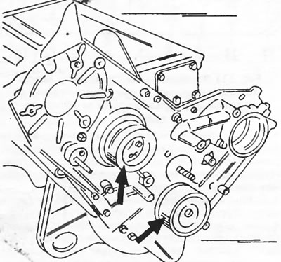
Figure 321. To center the shield holes relative to the shafts when installing the front cover, two centering tools are used.
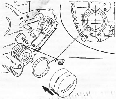
- Press new seals into the three holes of the bearing shield. Lubricate the sealing lips of the oil seals with engine oil and press them in using tubes of the appropriate diameters in the required position. Figure 322 shows the places where the seals are pressed in. The crankshaft toothed pulley oil seal has a mark on one side that must be in the position shown in Figure 323 after installation. Otherwise, the oil seal will not perform its functions. In addition, do not allow the seal lips to become deformed.
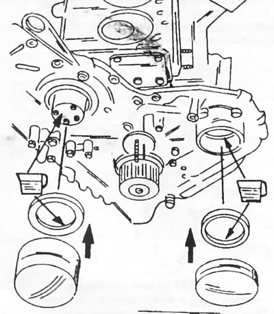
Figure 322. Installing oil seals. The seals are pressed in using a tool of the appropriate diameter.
- Tighten the lower crankcase bolts evenly in a circle to a torque of 16 Nm.
- Place a new gasket on the bottom of the crankcase and screw the oil pan on. Pay attention to the position of the special bolt. In the top view it should be located at the top left, approximately in the middle. Tighten the bolts to a torque of 11 Nm.
- Install the assembled oil pump with a new gasket. Place a new O-ring on the pump flange surface. Tighten the bolts to a torque of 15 Nm. Pump installation is shown in Figure 324.
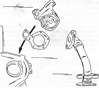
Figure 324. Installing the oil pump.
- Press a new oil seal into the oil pump hole.
- Place the flywheel on the crankshaft and press in a new pilot bearing. Lubricate the flywheel bolts with Loctite and tighten evenly in a circle to a torque of 90 Nm.
- Place the driven clutch disc into the flywheel and install the clutch basket. Center the position of the driven disk with a centering rod and cross-tighten the clutch mounting bolts to a torque of 33 Nm.
- Install the high pressure fuel pump without tightening the bolts.
Install the toothed pulleys shown in Figure 314:
- Tighten the toothed flywheel (1) to a torque of 60 Nm.
- Tighten the toothed flywheel (2) with three bolts to a torque of 34 Nm.
- Tighten the toothed flywheel (3) with three bolts to a torque of 21 Nm.
- Turn the engine until the ignition timing mark on the flywheel is aligned with the mark on the cylinder block.
- Turn the camshaft until the ignition timing mark on the flywheel (A) in Fig. 325 is set against the bolt (2).
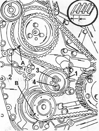
Figure 325. Attaching the timing belt. References to digital and letter designations are given in the text.
- Place the engine front side up and place the toothed belt on the toothed pulleys. After placing the timing belt on the tension roller (1), there should be 35 belt teeth between mark (A) and mark (B).
- After this, tighten the timing belt. At service stations, a device is used that is inserted into the tension roller, as shown in Figure 326. In this case, the load is secured on the second groove. After releasing the device, it moves under the weight of the load and tightens the belt to a specified value. If there is no such device, the roller should be moved so that the belt on the upper side can move a little more.
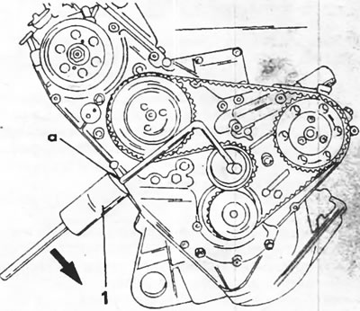
Figure 326. Tensioning the toothed belt to a specified value. The load (1) of the device must be installed with its side "a" on the second groove of the rod. The bent end of the rod is inserted into the tension roller.
- Tighten nut (3) in Fig. 325 to 32 Nm and then nut (4) to 21 Nm.
- Install the belt damper at the bottom right at a distance of 0.5–1.0 mm from the toothed belt.
- Turn the crankshaft two revolutions and check that the marks on the flywheel, camshaft and crankshaft are positioned as shown in Figure 325.
- After this, the high-pressure fuel pump is installed. First, the high-pressure fuel pump should be set for injection timing in accordance with the instructions in the relevant section for these engines (see section 23).
- Turn the engine until the marks on the flywheel and on the cylinder block align, as shown in Figure 327.
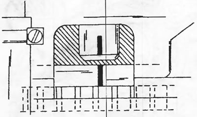
Figure 327. The marks on the flywheel and on the cylinder block must match.
- Install and slightly tighten the pump belt tension roller.
- Place the toothed belt and press the roller from below against the belt. Tighten the nut to a torque of 18 Nm. Then press the belt with your finger. The tension must correspond to the data shown in Figure 328.
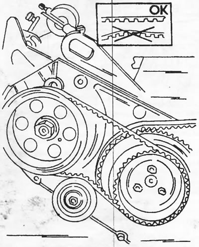
Figure 328. High-pressure fuel pump belt
- Turn the crankshaft two revolutions and check the position of all marks.
- Install the lower and then the upper timing belt cover. Tighten all bolts to a torque of 10 Nm.
- Next, the cylinder head is installed. The relevant instructions are given in section 20.4.4. It is imperative to install the correct gasket (according to the engine number).
- Install the rocker shaft. These works are also described in section 20.4.4.
- Adjust valve clearances (section 20.4.5).
- Install the cylinder head oil line, connect the diagnostic connector wiring harness, install the top dead center sensor and screw in the dipstick tube.
- Connect the idle speed control cable and adjust the cable according to the instructions in the section "Diesel fuel injection device".
- Connect the injection pipes. Tighten the nuts to 22.5 Nm, the hollow bolts to 10 Nm and the union nuts to 25 Nm.
- Install the cylinder head cover with a new gasket. Tighten 5 bolts to 11 Nm.
- Screw on the oil filter base with a new O-ring. Screw in the temperature switches with new sealing rings and tighten to a torque of 33 Nm. If there is an oil cooler, install it on the base (with a new gasket) and tighten the coupling sleeve to a torque of 85 Nm. Lubricate the oil filter gasket with engine oil and screw the filter in. Tighten the filter to a torque of 11 Nm. If there is no oil cooler, tighten the filter on the base to the same torque.
- Connect the connecting hose with two new fitting gaskets (Figure 329). Install the second hose between the engine and the cylinder block. Tighten the lower hollow bolt to 38 Nm.
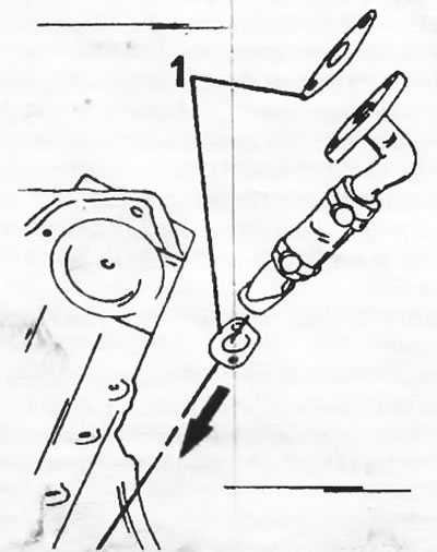
Figure 329. Installing the connecting hose. Both gaskets (1) must be replaced.
- Install the exhaust manifold with new gaskets (23 Nm) and bolt on the turbocharger (42 Nm). The mounting details are shown in Figure 330.
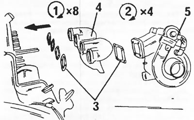
Figure 330. Installing the exhaust manifold. 1. Exhaust manifold nuts, 23 Nm; 2. Turbocharger nuts, 42 Nm; 3. Gaskets (new); 4. Exhaust manifold; 5. Turbocharger
- Install the intake manifold with new gaskets (18 NM) and screw the elbow on the outside with a new gasket (23 NM). The fastening is shown on figure 312.
- The remaining work is carried out in reverse order. After warming up the engine and letting it cool for 3 hours, tighten the cylinder head bolts again. At the same time, also check and, if necessary, adjust the valve clearances.
- Fill the engine with the prescribed amount of oil.