



- Unscrew the vacuum pump from the side of the cylinder head and remove the gasket.
- Unscrew the thermostat housing and disassemble it into the parts shown in Figure 332.
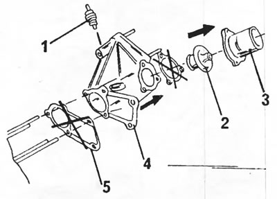
Figure 332. Thermostat parts. 1. Temperature switch; 2. Thermostat; 3. Thermostat housing cover; 4. Thermostat housing; 5. Gasket (must be replaced)
- Remove the plate (5 bolts) from the edge of the cylinder head, remove the gasket and pull out the tube.
- Remove four injectors. They are attached with plates. The enclosed O-rings should be discarded.
- Unscrew the current busbar from the glow plugs and remove the glow plugs.
- Unscrew the cold engine starting device temperature switch on the side of the cylinder head. Remove and discard the gasket. There is an adapter under the switch that also needs to be unscrewed. Remove and discard the gasket.
- A valve puller is required to remove the valves. A puller for diesel engines is shown in Figure 333. Compress the valve springs and use pliers to pull out the valve spring retainers (6). Unload the valve puller and remove the valve spring cups (5) and valve springs (4) one at a time. Pull out the valves (1) from the other side.
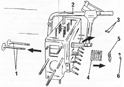
Figure 333. Disassembling the cylinder head. 1. Valves; 2. Valve puller; 3. Valve oil-reflecting rings; 4. Valve springs; 5. Valve spring cups; 6. Rusks
If you don't have a valve puller, you can remove it as follows:
- Place a block of wood into the combustion chamber so that it rests against the valve to be removed.
- Place a piece of tubing of the same diameter as the valve spring cup against the top of the valve spring cup and strike the tubing sharply with a hammer. At the same time, the valve spring is compressed and both crackers are released.
- Remove the valve parts and pull the valve out from the other side of the cylinder head. Immediately mark the installation position of the valves accordingly and fold the removed valves in the appropriate order.
- Use a screwdriver or tweezers to remove the oil deflector rings from the ends of the guide bushings. Only new rings must be installed.
- Clean the cylinder head with an oil-dissolving agent.
- Check the parts according to the following instructions. The instructions apply to both diesel and turbodiesel engines except for certain dimensional values. Therefore, it is imperative to take the specified values from the size and adjustment tables. The specific parameters are the same for both engine types.
Valves
Minor damage to the valve surfaces can be repaired by lapping the valves in the cylinder head seats, as described in the "Valve Seats" section. Measure the valves to ensure they comply with the dimensions and adjustment chart, and replace any valves that are out of tolerance.
- If the ends of the valve stems are worn, they can be processed on a grinding machine, provided that the correction requires removing no more than 0.50 mm of material.
- The valve heads are processed on a special machine for grinding valves, provided that the thickness of the valve head, shown by the arrows in Figure 334, after processing will be at least 0.5 mm.
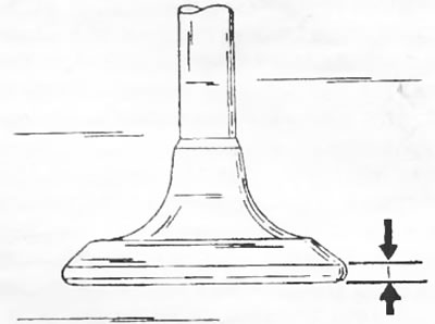
Figure 334. The thickness of the valve head between the two arrows must not be less than the specified size.
- Check the valve stems and therefore the inside diameter of the valve guides, which requires a standard micrometer and an inside diameter micrometer. To do this, measure the valve stems in various places using the method shown in Figure 335. After this, measure the corresponding valve guide as shown in Figure 336. If there is wear, i.e., the difference in dimensions is more than 0.10 mm, the guide bushings should be replaced (see the "Guide Bushings" section). The exhaust valve stem diameter is approximately 1.0 mm larger than the intake valve stem diameter.
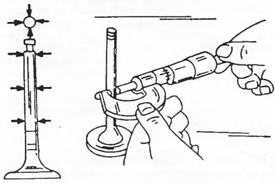
Figure 335. Measuring the valve stem diameter. The measurement locations are shown on the left. The valves with the larger diameter are exhaust valves. They also have a smaller valve head diameter.
Valve seats
- Check all valve seats for signs of wear and build-up. Minor wear can be eliminated with a 45° cutter. The intake and exhaust valves have the same angle. If there is significant wear, the valve seats must be re-milled or the valve seat rings must be replaced. The final work involves drilling out the receiving holes for the seats and must be done in a special workshop.
- When installing new valve guides, milling of the valve seats is required. For this, an angle cutter is used, the same as shown in figure 65, but having an angle of 45°.
- Mill the valve corner and then lightly finish the top edge of the valve seat with a corner mill to reduce the valve seat width to 2.5 mm. Finish milling once the seat reaches the specified width.
- Lapping the machined valve seats. To do this, apply a little grinding paste to the surface of the seat and insert the valve into the corresponding seat. Place a suction cup on the valve and turn the valve as shown figure 66.
- After lapping, clean all parts from dirt and grinding paste and check the valve head seat and seat ring. Both parts should show a continuous matte ring that defines the valve seat width.
- Apply a few strokes with a pencil to the ring on the valve head. The strokes should be applied at a distance of approximately 1 mm around the circumference. After this, carefully insert the valve into the guide sleeve and turn the valve 90°, while lightly pressing on the valve.
- Remove the valve and check if the ring marks on the valve head ring have disappeared. If the width of the valve seats is within the specified limits, installation can be performed. Otherwise, the valve seats will need to be machined or, in the worst case, the cylinder head will need to be replaced. In this case, all parts are removed from the old cylinder head and transferred to the new one.
In addition to this, on a diesel engine it is necessary to take into account the following:
To avoid mutual impacts between pistons and valves, the surfaces of the valve heads must be a certain size lower than the surface of the cylinder head. In Figure 339 this size is indicated by arrows. It is 0.7 mm for all valves. To check the valve installation depth, the following steps should be performed:
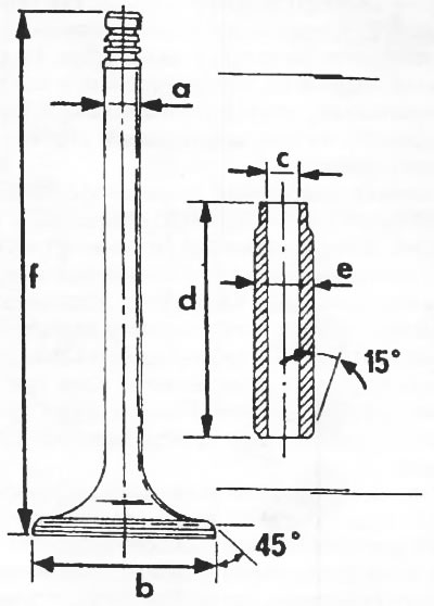
Figure 337. Measure the valves and guide bushings in the indicated locations. On diesel and turbodiesel engines the valve sizes are the same. a = valve stem diameter; b = valve head diameter; c = inner diameter of valve guide bushing; d = valve guide length (the exhaust valve sleeve is longer); e = valve guide outer diameter; f = valve length
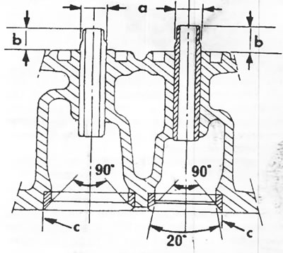
Figure 338 Sectional view of the inlet (A) and outlet (B) valve seats and guide bushings. a = receiving hole in the cylinder head; b = guide bushing protrusion size; c = valve seat diameter
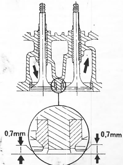
Figure 339. The cylinder heads must be below the cylinder head surface by the dimension indicated by the arrows.
- Mill out the valve seats in small portions, remove the metal shavings and insert the valve into the hole.
- Place a dial indicator on the cylinder head on the appropriate stand, as shown in figure 253, and apply the measuring probe to the clean surface of the cylinder head. The figure shows an indicator used at service stations, but any pointer indicator on a suitable stand will do. Reset the instrument scale to zero.
- Without changing the position of the indicator, move the measuring probe to the upper surface of the valve head. The indicator scale shows how much lower the valve head is located than the cylinder head surface. The figure shows the measurement of the exhaust, i.e. smaller, valve.
- Take measurements on the intake valves.
- Evaluate the measurement result and, if necessary, continue milling. However, before making a decision, you should check for cylinder head distortion.
To replace the valve seats, it is necessary to mill out the old valve seat. Since this is a complex job, it should be entrusted to a special workshop.
- Repeat the same measurement on the cylinder head prechamber liners. To do this, attach the measuring probe to the end of the pre-chamber. The pre-chamber liner should protrude by 0 to 0.3 mm (see Figure 254). If this is not the case, the pre-chambers must be replaced.
Valve springs
Everything that was given for gasoline engines also applies to diesel engines. Valve springs for intake and exhaust valves, as well as diesel and turbodiesel engines, are the same. All measured parameters are given in the tables of sizes and adjustments. The length of the spring under load is especially important.
Valve guide bushings
To accurately measure valve guides and valve stems, a micrometer is required, the use of which is shown in Figures 335 and 336. If the difference between two measurements exceeds 0.10 mm, the corresponding guide (or all of them) should be replaced. If a micrometer is not available (micrometer for measuring the internal diameters of valve guides), valve stem clearances can be determined as described for gasoline engines.
- Before replacing the guide bushing, check the general condition of the cylinder head.
- To replace the guide bushing, press out the old guide bushing using a suitable rod. In order to be able to knock out the valve guide, the cylinder head must be heated in hot water. Before pressing out the guide bushing, measure the bushing protrusion size from the top of the cylinder head (see Figure 338, dimension "b"). This dimension is different for intake and exhaust valves. The rod used to press out the guide bushings must have its neck machined to the inner diameter of the guide bushing.
- When replacing the guide bushings, it is necessary to replace the valves at the same time. This requires treatment of the valve seats.
- Lubricate the new guide bushings thoroughly with engine oil and press them into the cylinder head so that the protrusion is equal to the specified value (see size and adjustment tables).
- After pressing, adjust the diameter size to the specified value for the inlet and outlet valves. An adjustable sweep is used for processing.
When replacing the guide bushing, it is necessary to mill the valve seat. All guide bushings and valves are replaced at once.
Cylinder head
Thoroughly clean the adjacent surfaces of the cylinder head and block and check that the cylinder head is not warped. To do this, place a measuring ruler on the cylinder head and use feeler gauges to measure the gap between the ruler and the surface of the head along, across and diagonally. If a feeler gauge thickness greater than 0.10 mm can be inserted, as shown in Figure 340, the cylinder head must be milled, provided that no more than 0.7 mm of material is removed. The minimum permissible cylinder head height of 3 mm must be maintained. Otherwise, the cylinder head must be replaced.
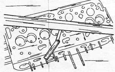
Figure 340. Measuring cylinder head tilt using a steel ruler and a set of feeler gauges.