



- Turn the engine until the exhaust valve of the first cylinder is fully open. In this position, adjust the intake valve of the third cylinder and the exhaust valve of the fourth cylinder. To easily turn the engine, lift the front wheel, engage one of the high gears and turn the wheel until the engine is in the desired position. The second wheel must be on the ground. To relieve compression, you can screw in the spark plugs.
- Crank the engine until the next exhaust valve opens. The valve adjustment is carried out in accordance with the table below and using Figure 346, which also shows the positions of the camshaft cams. The valves with crosses are exhaust valves, and the valves marked with a black circle are intake valves. The valves that need to be adjusted are shown on the right:
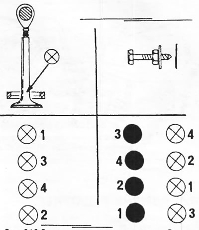
Figure 346. Adjusting valve clearances. The intake valves are marked with circles with a cross, and the exhaust valves are marked with black circles. When opening the corresponding inlet valve, adjust the valves indicated on the right side.
- Adjusting the valve clearances can also be done in another way, when the engine is turned until both valves of the first cylinder are completely closed. This position can be controlled by the fourth cylinder, the valves of which must intersect. When turning the engine from this position in both directions, it is visible that one valve of the fourth cylinder rises and the other valve falls. In this position, the rocker arms of the first cylinder have clearances and both camshaft cams are in the position shown in Figure 347. After adjusting the valve clearances of the first cylinder, the engine is turned another half turn and the next pair of closed valves is adjusted. The following table shows the valve clearance adjustment diagram:
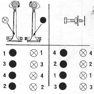
Figure 347. Adjusting valve clearances when the valves of the cylinders indicated on the left are closed. The valve clearances of the cylinders indicated on the right are adjusted.
- To check the valve clearance, insert a feeler gauge of the required thickness between the end of the valve stem and the rocker arm at locations (A) and (B) in Figure 348. To adjust the clearances of the intake valves (A), a feeler gauge with a thickness of 0.30 mm is required; to adjust the exhaust valve clearances (B), a 0.20 mm feeler gauge is required. The clearance tolerance for all valves is ±0.05 mm. The feeler gauge should fit easily, but not too loosely, into the gap. A sign of good adjustment is when the feeler gauge enters without jamming, bends slightly, and then jumps into the gap between the valve stem and the rocker arm.
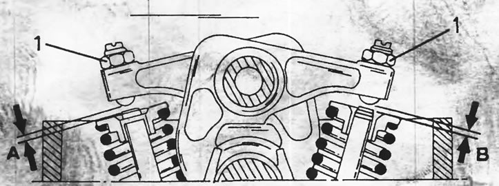
Figure 348. Adjusting valve clearances. The clearance on the intake valves (A) is set to 0.30 mm, and on the exhaust valves (B) - 0.20 mm. The tightening torque of the lock nut is 18 Nm.
- When adjusting the valve clearance, use a socket wrench to loosen the lock nut and a screwdriver to turn the adjusting screw. When tightening the lock nut, hold the adjusting screw to prevent it from coming loose. Tighten the nuts to a torque of 18 Nm.