



- Insert the valves into their guide bushings. If the valve seats have been machined, they must be installed in the corresponding bushings. The same applies to used valves, which must be installed in their original locations.
- Thoroughly clean the threaded holes for the cylinder head bolts. The holes must be dry and free of grease. If necessary, tap the threads. After this, thoroughly clean the threads.
- Install new valve stem seals on each guide bushing.
- Insert valves (well lubricated with motor oil) into the cylinder head from the bottom and put the parts shown on top of each valve figure 333. Compress the springs with a special spring compressor. With the end of the valve stem protruding from the top side, use tweezers to insert the valve crackers. Slowly release the spring compressor and check that the valve springs are seated properly in the valves.
- Hit the top of the valve stems with a plastic hammer. At the same time, poorly seated crackers pop out. For safety, place a rag on the ends of the springs to prevent the parts from flying apart.
- Insert a tube into the side of the cylinder head, apply a new gasket and tighten the two bolts with new washers to a torque of 24 Nm.
- Install and tighten the cold start temperature switch adapter to 18 Nm. Screw in the temperature switch with a new gasket and tighten to the same torque.
- Screw in the temperature switch from the top of the head (28 Nm). Install a new gasket.
- Install the thermostat housing and thermostat using drawing 332. Install all new gaskets and O-rings. Tighten the three housing bolts to a torque of 20 Nm and the three housing cover nuts to a torque of 10 Nm. The temperature switch is secured to the housing with a tightening torque of 32 Nm.
- Screw in four glow plugs with a tightening torque of 20 Nm and connect the current bus.
- Insert and slightly tighten the four injectors with new washers. Ensure washers are installed correctly. Align the injectors according to Figure 341.
- Assemble from the other end of the cylinder head in accordance with Figure 342. Tighten the 5 nuts to a torque of 20 Nm.
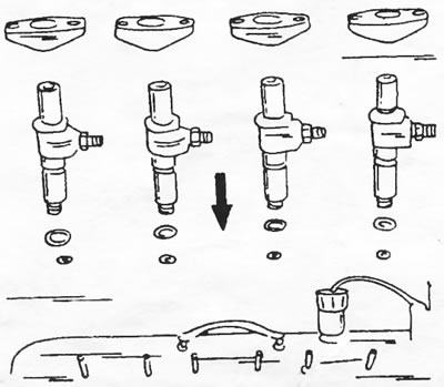
Figure 341. Installing injectors. The joints must be located in the specified position.
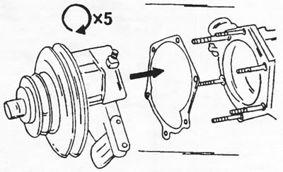
Figure 342. Tighten the 5 nuts securing the vacuum pump assembly to the belt pulley to a torque of 20 Nm. Be sure to replace the gasket.
Source available here: peugeotbook.ru