



- Thoroughly clean the threaded holes for the cylinder head bolts. The holes must be dry and free of grease. If necessary, tap the threads. After this, thoroughly clean the threads.
- Turn the crankshaft so that all four pistons are in the holes approximately in the middle.
- Place the cylinder head in a dry condition (do not lubricate with motor oil). The cylinder head gasket is marked (L25) on the strip (Figure 343) and only the gasket with the required markings can be installed. When ordering a cylinder head, it is best to specify the engine number. The gasket must be installed so that the marking is visible from above.
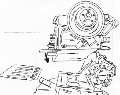
Figure 343. Installing the cylinder head. There is a gasket marking on the bar (1).
- Position the cylinder head as shown in Figure 343 and screw in the cylinder head bolts. The toothed sides of the washers must face the cylinder head.
- Tighten the cylinder head bolts. Tightening of bolts is carried out in the sequence indicated on figure 331.
- Tighten the bolts in the sequence shown to a torque of 110 Nm.
- After this, tighten the bolts in the specified sequence to a certain angle without using a torque wrench. This type of tightening typically requires a protractor, the use of which is shown in Figure 344. These protractors are manufactured by FACOM. The tightening angle is 100°, or slightly more than a quarter turn. This angle can be easily maintained by attaching an extension handle.
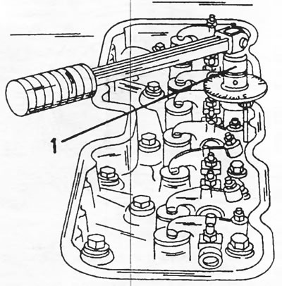
Figure 344. Using a protractor to tighten cylinder head bolts. The protractor is installed between the wrench head and the torque wrench. When tightening to a certain angle, lock the torque wrench.
- Tighten the bolts again in the specified sequence by 100°. Additionally, tightening the bolts after a certain period of engine operation is required, as described at the end of this section.
- Assemble the rocker shaft if it was disassembled. To hold the two rocker arms on the shaft, special clamps are used. We are talking about "U"-shaped clamps made of sheet metal, which can be made according to Figure 345.

Figure 345. Assembling the rocker shaft. The clamps shown below are used to install two rocker arms. 1. Exhaust valve rocker arm; 2. Intake valve rocker arm; A = Clamp; a = lubrication hole
The assembly is carried out as follows:
- The large oil hole should be located on the right side. Install the washer, intake valve rocker arm (1), washer, spring, exhaust valve rocker arm (2) and another washer. Place the clamp (A) on both rocker arms installed on the shaft so that both rocker arms cannot move apart under the action of the spring being placed on them.
- Install the remaining rocker arms in accordance with the arrangement shown in Figure 345.
- Lubricate the push rods with engine oil and insert the push rods into the cylinder block.
- After this, install the assembled rocker shaft in the cylinder head. A large oil hole is located on the water pump side. The oil holes in the shaft must face the cylinder head, meaning the shaft may need to be turned. The spherical rocker arm cups must be engaged with the pushrods.
- Install the rocker shaft brackets and screw in the bolts. Tighten the bolts evenly to a torque of 25 Nm. Once the bolts are tightened, you can remove the rocker arm clamps.
- In accordance with the instructions section 20.4.5 adjust valve clearances.
- Install the cylinder head cover with a new gasket.
- Connect the cylinder head oil line.
- Screw on the diagnostic connector with the bracket.
- Connect the injection pipes, check that they are freely positioned and tighten the union nuts to a torque of 25 Nm.
- Connect the hose to the cylinder head cover.
- Adjust the tension of the water pump, vacuum pump and alternator belts.
- Install the belt cover.
- Connect the hose to the air intake.
The remaining work is carried out in reverse order, but the following should be briefly mentioned:
- Connect the muffler pipe. The ball joint is lubricated with Gripcott heat-resistant grease or similar grease. Tighten the manifold nuts until the coils of the inserted springs are compressed. From this position, loosen the nuts exactly half a turn.
- Connect the fuel return hose to the fuel tank.
- Connect the water hoses to the cylinder head.
- Connect the throttle cable and the cold starter cable.
- Install the radiator grille and secure it with two bolts and nuts.
- Connect the water hoses to the radiator.
- Install the rear spare tire mounting bracket.
- Attach the engine compartment hood lock to the radiator grille and make sure it functions properly. Otherwise, make the necessary adjustments.
- Connect the electrical wires of the following consumers: temperature switch on the radiator, temperature switch on the water pump, cooling fan, lighting system and turn signals, glow plugs, engine stop solenoid valve, ground wire of the diagnostic connector and both battery wires.
- Install the right engine mount. Tighten the bolts to a torque of 50 Nm. Remove the jack.
- Fill the coolant and bleed air from the cooling system.
- If the cylinder head gasket replacement was caused by a blown gasket, the engine oil should be changed, as coolant may have entered the engine crankcase.
Tightening the cylinder head bolts:
- Start the engine and leave it running until the radiator fan turns on, that is, when the engine is warmed up.
- Turn off the engine and let it cool for 3 hours.
- Tighten all cylinder head bolts in the sequence shown on figure 331, at an angle of 45°. Using a protractor, this is relatively simple. Without using a protractor, tighten the bolts by half a quarter turn. You can apply appropriate marks on the cylinder head.
- Check and, if necessary, adjust the valve clearances in accordance with the instructions in the next section.
Original published on the portal: peugeotbook.ru