



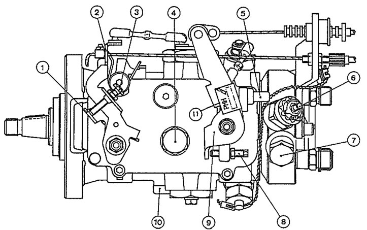
1.1a. Lucas fuel injection pump adjustment points and other features 1. Stop lever; 2. Fast idle lever; 3. Idle speed adjustment screw; 4. Fuel return hose union; 5. Maximum speed adjustment screw; 6. Stop solenoid; 7. Fuel inlet hose union; 8. Anti-stall adjustment screw; 9. Accelerator lever; 10&11. Injection pump timing value location
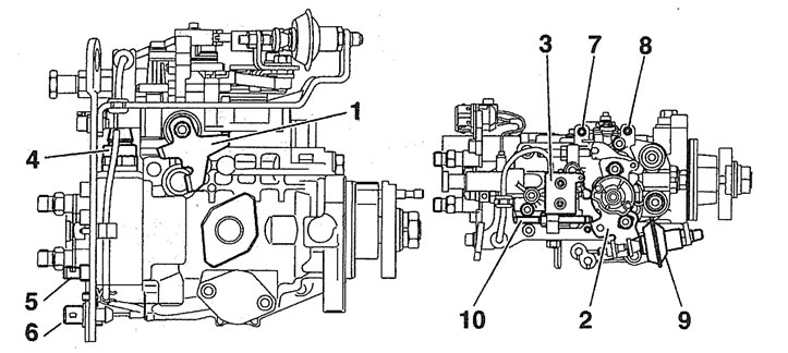
1.1b. Bosch fuel injection pump adjustment points and other features 1. Stop lever; 2. Load lever; 3. Load lever switch; 4. Stop solenoid; 5. Stop solenoid wiring connector; 6. Load lever switch connector 7. Idle speed adjustment screw; 8. Fast idle adjustment screw; 9. Damping vacuum capsule 10. Residual flow adjustment screw
The exhaust system is conventional, but on certain models, an unregulated catalytic converter may be fitted to reduce exhaust gas emissions.
Fuel is drawn from the fuel tank to the fuel injection pump by a vane-type transfer pump incorporated in the fuel injection pump. Before reaching the pump, the fuel passes through a fuel filter, where foreign matter and water are removed. Excess fuel lubricates the moving components of the pump and is then returned to the tank.
The fuel injection pump is driven at half crankshaft speed by the timing belt. The high pressure required to inject the fuel into the compressed air in the swirl chambers is achieved by a cam plate acting on a single piston on the Bosch pump, or by two opposed pistons forced together by rollers running in a cam ring on the Lucas pump. The fuel passes through a central rotor with a single outlet drilling which aligns with ports leading to the injector pipes.
Fuel metering is controlled by a centrifugal governor, which reacts to accelerator pedal position and engine speed. The governor is linked to a metering valve which increases or decreases the amount of fuel delivered at each pumping stroke.
Basic injection timing is determined when the pump is fitted. When the engine is running, it is varied automatically to suit the prevailing engine speed by a mechanism which turns the cam plate or ring.
The four fuel injectors produce a homogeneous spray of fuel into the swirl chambers located in the cylinder head. The injectors are calibrated to open and close at critical pressures to provide efficient and even combustion. Each injector needle is lubricated by fuel, which accumulates in the spring chamber and is channelled to the injection pump return hose by leak-off pipes.
Bosch or Lucas fuel system components may be fitted, depending on the model. Components from the latter manufacturer are marked either "CAV", "Roto-Diesel" or "Con-Diesel", depending on their date and place of manufacture. With the exception of the fuel filter assembly, replacement components must be of the same make as those originally fitted.
Cold starting is assisted by preheater or "glow" plugs fitted to each swirl chamber (see Chapter 5C for further details).
The fast idle system is operated by a thermostatic valve which is screwed into the fuel filter/thermostat housing. The valve operates a fast idle iever on the injection pump, via a cable, to increase the idle speed when the engine is cold.
A stop solenoid cuts the fuel supply to the injection pump rotor when the ignition is switched off. On some pumps, there is also a hand-operated stop lever for use in an emergency.
Provided that the specified maintenance is carried out, the fuel injection equipment will give long and trouble-free service. The injection pump itself may well outlast the engine. The main potential cause of damage to the injection pump and injectors is dirt or water in the fuel.
Servicing of the injection pump and injectors is very limited for the home mechanic and any dismantling or adjustment other than that described in this Chapter must be entrusted to a Peugeot dealer or fuel injection specialist.
Note: The fuel system component photographs appearing throughout this Chapter depict the Lucas fuel injection pump and associated equipment which is fitted to the majority of TUD 3 and TUD 5 models. The Bosch fuel injection pump is an alternative fitment on 1997-on TUD 5 models for certain territories. At the time of writing very little specific information exists on the Bosch equipment but the procedures contained in the text are applicable to both, unless otherwise stated.
Warning: It is necessary to take certain precautions when working on the fuel system components, particularly the fuel injectors. Before carrying out any operations on the fuel system, refer to the precautions given in "Safety first!" at the beginning of this manual and to any additional warning notes at the start of the relevant Sections.