
2. Engage the handbrake and first gear. Remove one of the wheel nuts and the hub cap. Loosen and remove the hub nut. Remove the puck underneath. Loosen the 2 remaining wheel nuts.
3. Working under the machine, clean the surfaces near both ends of the drive shaft of dirt and grease. When removing the drive shaft, it is extremely important that dirt does not get into exposed bearings, etc. Take measures to ensure that the shaft does not come out of the final drive housing on its own at the initial stages of its removal. There is a special tool for this "Peugeot", however, you can do without it by wrapping the shaft itself and the bolts on the differential box with wire.
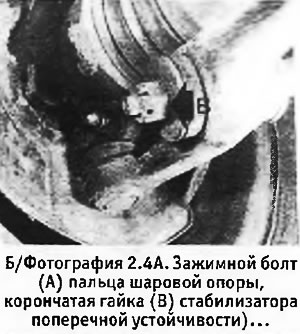
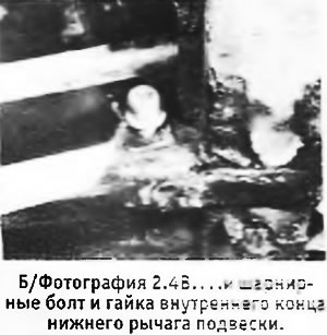
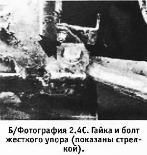
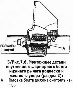
4. Unscrew the clamping nut of the ball joint pin (above the outer end of the lower suspension arm). Remove the cotter pin and castle nut with washers from the end of the anti-roll bar that protrudes through the lower control arm. Remove the nut from the pivot bolt at the inner end of the lower control arm. Unscrew and remove the rear bolt securing the hard stop above the hinge bolt of the inner end of the lower suspension arm (see pictures).
 |  |
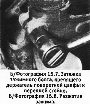
5. Remove the clamp bolt from the outer end of the lower suspension arm, remove the hard stop from the inner end of the arm, and unscrew the pivot bolt at the inner end of the arm.
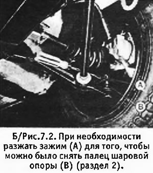
6. Install the jack just behind the front wheel arch, jack up the front of the machine and support it securely. Pull the inner end of the lower suspension arm out of its mounting bracket and place a 120mm wood block under the front wheel. Lower the machine onto the wheels and remove the ball joint pin from its clip. If necessary, you can carefully open the clamp so that you can remove the finger (see b/fig. 7.2).
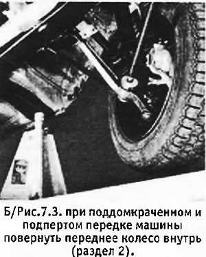
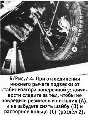
7. Raise and support the front of the machine again. Turn the front wheel inward and disconnect the lower suspension arm from the anti-roll bar. Be careful not to damage the ball joint rubber boot. Remove the spacer ring and washer from the stabilizer bar, paying attention to how they stood.
 |  |
8. Carefully rotate the front suspension strut outward while pulling the driveshaft splines out of the hub.
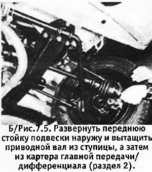
9. Remove the wire that attached the drive shaft, and turning the front wheel all the way outward, pull the drive shaft out of the final drive/differential housing. Be prepared for some oil to spill.
10. Remove the oil seals from the final drive/differential housing and from the hub. Both seals must be replaced with new ones.
11. Apply some grease to the new oil seal (with two sponges) and carefully hammer it into place in the final drive/differential case with the side with the spring inward. Fill the space between the seal lips with multipurpose grease. Install the new oil seal into the wheel hub in the same way, making sure it rests against the bearing circlip, and fill the space between the oil seal lips with multipurpose grease.
12. Before reinstalling the drive shaft, inspect it for obvious defects. Clean the splines on both ends of the shaft and apply a little Molykote 321 R to the splines on the hub side (or similar anti-friction lubricant).
13. Carefully insert the shaft into the final drive/differential housing, being careful not to damage the oil seal. Tie the shaft with wire to the differential so that it does not come out.
14. Insert the shaft into the hub, being careful not to damage the oil seal. Install thrust washer and new nut, but do not tighten the latter yet.
15. Install the spacer ring and washer on the anti-roll bar: making sure that they are exactly in their original position (see paragraph 7). Install the lower suspension arm onto the end of the anti-roll bar, being careful not to damage the ball joint rubber boot.
16. Insert the ball joint pin into its clamp on the hub and install the clamp bolt head back. Install the washer and castle nut to the anti-roll bar without tightening the nuts yet.
17. Install a hard stop on its bracket, put a new washer on the bolt and install the bolt in place with the head up. Slide the second washer onto the bolt and install the new Nylstop nut without tightening it yet.
18. Tighten the ball joint stud retaining bolt nut to the correct torque.
 |  |
19. Lower the machine to the ground. Now load the front end of the machine so that the hole in the rubber bushing on the inner end of the lower suspension arm aligns with the bolt holes in the arm mounting bracket. There is a special tool "Peugeot", which allows you to pull the car body down so that it presses on the springs when lifting the car with a lift. In principle, you can get by with several devices for compressing the springs. If you compress the front springs well, you will get the desired result. Alternatively, you can simply ask how many people to sit on the hood cover, thereby pressing down the front of the car. Once the hole in the bushing aligns with the holes in the mounting bracket, insert the inner pivot bolt head back and slide the washer and new Nylstop nut onto the bolt until tight. Remove the spring compressors or have a helper get off the bonnet and remove the wire holding the driveshaft to the differential.
20. Tighten the hub nut to the correct torque and use a suitable blunt punch to drive the collar of the nut into the groove on the shaft to lock it. Install the hub cap and third wheel nut. Tighten the wheel nuts to the correct torque.
21. Disengage the handbrake and set the gearshift lever to neutral. Rock the car back and forth to set the suspension, and then apply the handbrake again.
22. Install spring compressors on the front springs or load the front again so that there is a gap of 50 mm between the drive shafts and the edge of the wings. To achieve the desired clearance, you can take 2 wooden blocks 50 mm high and insert them between the drive shafts and the edge of the wings.
23. Tighten the lower control arm inner pivot bolt nut to the correct torque. Tighten the nut and bolt holding the hard stop to the correct torque.
24. Tighten the castle nut on the anti-roll bar to the correct torque. If the cotter pin hole does not align with the slot in the nut, tighten the nut a little more until it reaches the correct position, being careful not to exceed the maximum tightening torque. Install a new pin to 3 mm and lock the nut, then remove the spring compressors or remove the load from the hood.
25. Check front wheel alignment (see chapter 9).
26. Fill the engine with oil and connect the negative wire to the battery.