
Removing
Switch off ignition and disconnect a wire from the negative plug of the storage battery.
Remove the decorative casing from the engine.
Remove the plastic windshield cross member and soundproofing plates.
Disconnect the connector from the air flow meter.
At the outlet of the turbocharger, disconnect and remove the bent pipe.
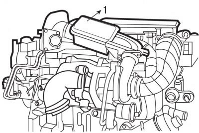
Pic. 4.28. Location and direction of removal of the resonator (1)
Turn out bolts and, having pulled up, remove the resonator 1 (pic. 4.28).
Remove the air intake duct.
Remove the blower air pipe.
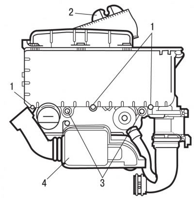
Pic. 4.29. Air filter: 1 - bolts; 2 - wire harness clamp; 3 - bolts; 4 - resonator
Release from clamp 2 (pic. 4.29) on the air filter cover and move the wiring harness aside.
Turn out bolts 1 and remove a cover of the air filter and the air filter.
Turn out bolts 3 fastenings of the case of the air filter and remove it.
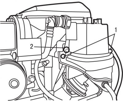
Pic. 4.30. Arrangement of bolts of fastening of a protective element of the fuel filter (1) and fuel filter (2)
Remove bolts 1 (pic. 4.30) fastening of the protective element of the fuel filter.
Loosen the tightening torque of bolt 2 and remove the fuel filter. Comply with cleanliness requirements.
Close the fittings with suitable plugs to prevent the ingress of dirt.
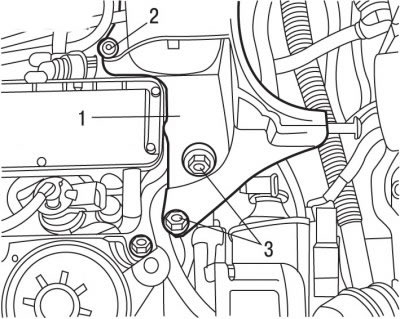
Pic. 4.31. Bolt location (2 and 3) bracket mounting (1) fuel filter
Turn out bolts 2 and 3 fastenings of an arm of the fuel filter 1 (pic. 4.31).
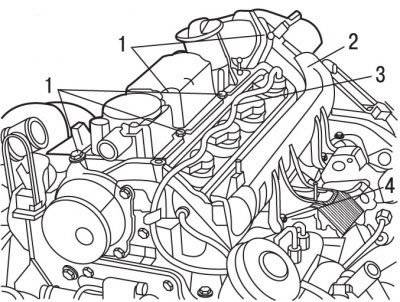
Pic. 4.32. Integrated air supply unit: 1 - bolts; 2 - lower block of the integrated air supply system; 3 - fuel return pipes; 4 - bolts
Turn out bolts 1 and 4 (pic. 4.32) fixing the unit of the integrated air supply system.
Disconnect the connectors from the injectors.
Disconnect the fuel return pipes 3 from the injectors. Seal the fuel return pipes with suitable plugs to prevent dirt from entering.
Remove the bottom block 2 of the integrated air supply system.
Using a special protective kit, close the air pipes and covers of the camshaft beds.
Installation
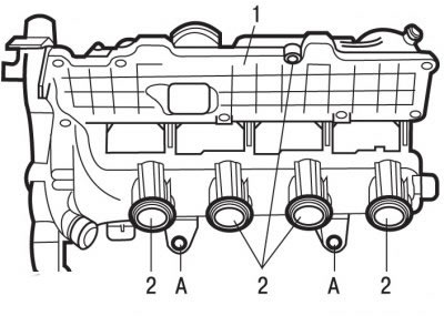
Pic. 4.33. Integrated air supply unit: 1 - block of the integrated air supply system; 2 - sealing rings; A - rubber stops
Replace o-rings 2 (pic. 4.33), after lubricating them with engine oil.
Replace block 1.
Check the presence of rubber stops A.
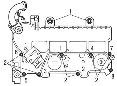
Pic. 4.34. Location and tightening sequence of bolts (1 and 2) fixing the integrated air supply unit
Insert bolts 1 and 2 (pic. 4.34) fixing the unit of the integrated air supply system.
Tighten bolts 2 in sequence (see fig. 4.34) torque 10 Nm.
Remove the plugs covering the fuel return pipes.
Connect fuel return pipes.
Connect the connectors to the injectors.
Connect the exhaust gas recirculation pipe.
Install the fuel filter mounting bracket 1 (see fig. 4.31) and secure it with screws. Tighten bolt 2 to 10 Nm and bolt 3 to 5 Nm.
Install the fuel filter and secure it with bolt 2 (see fig. 4.30), tightening it with a torque of 5 Nm.
Install the air filter housing.
Clip in clamp 2 (see fig. 4.29) air filter caps wiring harness.
Install the air intake duct.
Install the resonator after lubricating the O-ring with engine oil.
Install the blower air hose.
Install the windshield plastic cross member and soundproofing plates.
Install the decorative cover on the engine.
Connect the wire to the negative battery terminal.