



Table of contents: Removal 🠇 Installation 🠇
Removal
Turn off the ignition and disconnect the cable from the negative battery terminal.
Remove the integrated air supply system.
Disconnect the electrical connectors from the injectors.
Disconnect the fuel return pipes from the injectors. To prevent dirt from entering, close the fuel return lines with suitable plugs.
Use SODIMAC 35 to clean the high-pressure fuel pipe union nuts and the areas around the nuts.
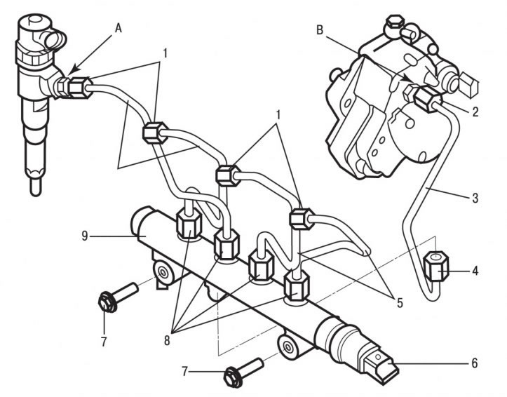
Figure 4.35. Location of fuel supply lines to the injectors: 1, 2, 8 - connecting nuts; 3 - high pressure fuel pipe; 4 - connecting nut; 5 - high pressure fuel pipes; 6 - high pressure sensor; 7 - bolts; 9 - fuel distributor (Common Rail); A - hexagon on the nozzle; B - hexagon on the high-pressure fuel pump
Holding the hexagons A with a wrench (figure 4.35) on the injectors, use the second key to unscrew the connecting nuts 1 securing the high-pressure fuel pipes 5 to the injectors.
Unscrew the connecting nuts 8 securing the high-pressure fuel pipes 5 to the fuel distributor and remove the fuel pipes. To prevent dirt from entering, close the fuel lines and fittings on the fuel distribution line with suitable plugs.
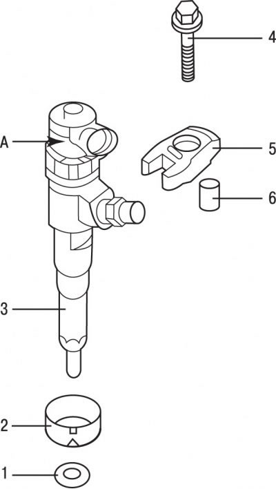
Figure 4.36. Nozzle: 1 - sealing ring; 2 - spacer; 3 - nozzle; 4 - bolt; 5 - bracket; 6 - bushing
Remove bolts 4 (figure 4.36), remove the injector mounting brackets 5 and, being careful, remove the injectors from the cylinder head.
Caution! Do not turn the injectors by the hexagon A (see figure 4.36).
Remove the sealing rings 1 and spacers 2 from the injectors.
Close the injector sockets and injector nozzles with suitable plugs.
Installation
Caution! When installing injectors, use new high-pressure fuel lines 5 (see Figure 4.35) and sealing rings 1 (see figure 4.36).
Remove the plugs covering the injector sockets.
Install new sealing rings on the injectors.
Install the injectors onto the cylinder head and secure them with brackets and bolts.
Install the high-pressure fuel lines onto the injectors and fuel distributor and secure them with the union nuts, first tightening them to a torque of 17 N·m and then finally tightening them to a torque of 22 N·m. When tightening the union nuts on the injectors, hold the Allen keys A with a wrench (see Figure 4.35).
Install an integrated air supply system.
Remove the air filter housing.
Connect the cable to the negative terminal of the battery.
Start the engine.
Check the tightness of the connections.
Increase engine speed to 3500 min⁻¹.
Check the tightness of the connections.
Install the air filter housing.
Install the decorative cover on the engine.