
The nozzles are fastened with brackets.
The cylinder head cover is made of plastic with an integrated oil filler neck and crankcase ventilation system inlet.
Cylinder head gaskets are edged in stainless steel and are available in five thicknesses.
Removal of a head of the block of cylinders spend on the cold engine.
Attention! Replace all clamps and clamps that are damaged or cut during removal with new ones when installing the head of the block. When replacing the block head, fill the cooling system with fresh coolant.
Removing
Switch off ignition and disconnect a wire from the negative plug of the storage battery.
Drain the coolant.
Remove the accessory drive belt.
Remove the toothed belt.
Remove the decorative casing from the engine.
Remove the plastic windshield cross member and soundproofing plates.
Disconnect the connector from the air flow meter.
At the outlet of the turbocharger, disconnect and remove the bent pipe.
Remove the integrated air supply unit.
Using a special protective kit, close the air pipes and covers of the camshaft beds.
Remove the heat shield and catalytic converter.
Disconnect the EGR valve pressure relief pipe.
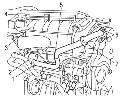
Pic. 4.2. Pipe and valve of the exhaust gas recirculation system: 1 - clamp; 2 - bolts; 3 - air filter housing; 4 - air filter cover; 5 - bolt; 6 - bolts; 7 - tube
Turn out bolts 2, 5 and 6 (pic. 4.2), loosen the clamps 1 and remove the tube of the exhaust gas recirculation system.
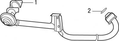
Pic. 4.3. EGR pipe: 1 - metal seal; 2 - sealing ring
Remove with the subsequent installation of a metal seal 1 (pic. 4.3) exhaust gas recirculation valves and O-ring 2.
Remove the jumpers connecting the glow plugs.
Remove glow plugs.
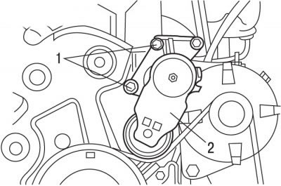
Pic. 4.4. Bolt location (1) tension roller attachment (2) accessory drive belts
Remove bolts 1 (pic. 4.4) and remove the tension roller 2 of the accessory drive belt.
Disconnect from the generator contact sockets.
Turn out bolts of fastening and remove the generator from the engine.
Turn out bolts and remove the top support of the generator.
Turn out the top bolts of fastening of a support of the high pressure fuel pump.
Clean off dirt from the fuel supply pipes.
Turn away from atomizers and a distributive fuel pipeline (Common Rail) high pressure pipelines. To prevent dirt from entering, close the pipes and fittings on the fuel distribution pipe with suitable plugs.
Turn out bolts, remove fastening brackets of atomizers 5 and, being careful, take atomizers from a head of the block of cylinders.
Close the injector sockets and injector nozzles with suitable plugs.
Remove the coolant outlet block and set it aside.
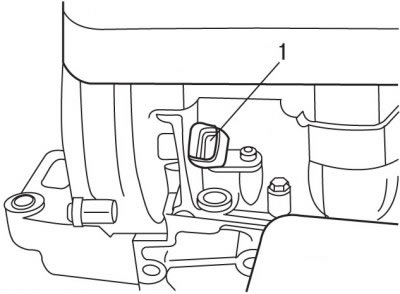
Pic. 4.5. Sensor location (1) camshaft position
Remove camshaft position sensor 1 (pic. 4.5).
Pic. 4.6. Bolt location (1) camshaft bearing caps
Remove bolts 1 (pic. 4.6) fastening of covers of beds of a camshaft.
Disconnect the vacuum pump pressure relief tube.
Remove the camshaft bearing cap.
In the reverse order to tightening, gradually loosen and then completely unscrew the cylinder head bolts.
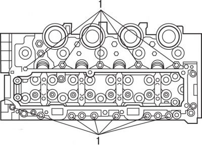
Install curved levers in the holes of the cylinder head and, by pressing them, separate the head from the cylinder block.
Remove the cylinder head and place it on a soft base.
Preparing the block head for installation
The mating surfaces of the head and cylinder block must be perfectly clean. Use a hard plastic or wooden scraper to clean them. Be careful when cleaning as aluminum alloy is very easy to damage. Make sure that carbon deposits do not get into the channels of the lubrication and cooling system. This is especially important for the lubrication system, as deposits can block the oil supply to engine parts. Clean channels if necessary.
Check the mating surfaces of the head and cylinder block: they should not have nicks, deep scratches or other damage. Small defects can be eliminated by machining. In case of significant defects, the parts must be replaced.
Using a metal ruler and feeler gauge, check the flatness of the mating surfaces.
If the flatness deviation exceeds 0.05 mm, the head must be reground.
Clean the threads of the cylinder head bolt holes.
Clean the bolt holes in the block. Screwing a bolt into an oil-filled hole can rupture the block due to hydraulic pressure.
Before reusing the bolts, measure the length of the bolts to the base of the head, which should be no more than 149.0 mm.
Installation
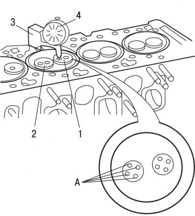
Pic. 4.7. Valve protrusion measurement: 1 - exhaust valve; 2 - inlet valve; 3 - stand; 4 - dial indicator; A - measurement points
Check the protrusion of the valves in relation to the plane of the cylinder head at points A (pic. 4.7), which should be equal to 1.25 mm. The protrusion value must be calculated as an average based on four measurements.
Remove the device that fixes the crankshaft from turning.
It is necessary to measure the protrusion of the pistons from the cylinder block and, in accordance with this value, select the thickness of the new cylinder head gasket.
Note. The maximum difference between the protrusions of the pistons must be less than 0.10 mm.
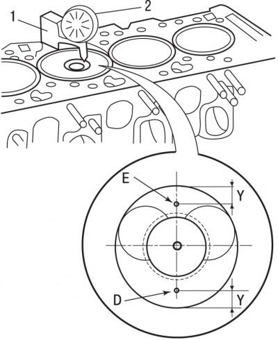
Pic. 4.8. Measurement of piston protrusion from the cylinder block: 1 - stand; 2 - dial indicator; D, E - measurement points; Y = 10.0 mm
Install a dial gauge 2 on the cylinder block (pic. 4.8) on stand 1.
Install the indicator's measuring tip on the upper plane of the cylinder block and set the indicator needle to 0.
Install the measuring tip of the indicator on one of the control points.
Turn the crankshaft until one of the pistons reaches TDC, but do not go over it. Read the piston protrusion value on the indicator.
The protrusion value must be calculated as an average based on measurements at two points.
Measure the protrusion of the other pistons in the same way.
The largest average piston protrusion determines the thickness of the cylinder head gasket.
Use the special tool to secure the flywheel from turning.
Check for the presence of dowel sleeves in the cylinder block.
A new cylinder head gasket must be removed from the packaging immediately before installation.
Install a new cylinder head gasket having a predetermined thickness.
Install the cylinder head.
Lightly coat the threads of the cylinder head bolts with MOLYKOTE G RAPID PLUS grease, insert the bolts and hand-tighten.
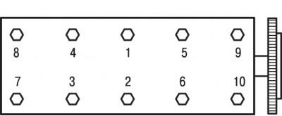
Pic. 4.9. Cylinder head bolt tightening sequence
In the sequence shown in fig. 4.9, tighten the cylinder head bolts in several stages:
- 1st stage - tighten with a torque of 20 Nm;
- 2nd stage - tighten with a torque of 40 Nm;
- 3rd stage - tighten by an angle of 230.
Install the coolant outlet unit with a new gasket and secure with bolts, tightening them to 10 Nm.
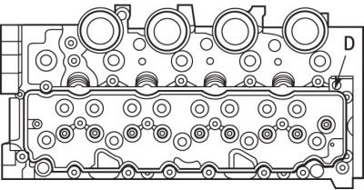
Pic. 4.10. Place (D) applying SILICONE CATEGORIE 2 sealant to the mating surface of the cylinder head
Apply SILICONE CATEGORIE 2 all around the mating surface (pic. 4.10).
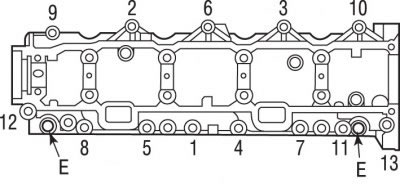
Pic. 4.11. The sequence of tightening the bolts of the camshaft bearing cap: E - holes for installing special devices
Install in holes E (pic. 4.11) camshaft bearing caps with the special tools and install the cap in place.
In the sequence shown in fig. 4.11, tighten and then tighten the camshaft bearing cap bolts to 10 Nm.
Remove special tools from holes E.
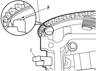
Pic. 4.12. Sensor installation (1) camshaft positions: F - sensor head
Install camshaft position sensor 1 (pic. 4.12).
Adjust the gap between the pulley and the sensor so that it is 1.2 mm. If a new sensor is being installed, move crown F to adjust the air gap (pic. 4.12) sensor until one of the three projections on the camshaft pulley touches.
Connect the vacuum tube to the vacuum pump.
Install nozzles and connect high pressure lines.
Install the fuel pump support on the cylinder head and secure with bolts, tightening them to a torque of 20 Nm.
Establish the generator top support and fix bolts, having tightened them the moment of 20 Нм.
Install the generator and secure with bolts, tightening them with a torque of 40 Nm.
Install the tension roller and secure with a bolt, tightening it with a torque of 20 Nm.
Screw in the glow plugs and tighten to 9 Nm.
Install the jumpers connecting the glow plugs.
Install the valve and tube of the exhaust gas recirculation system and secure them with bolts and clamps.
Install the catalytic converter and heat shield.
Install the integrated air supply unit.
Install the accessory drive belt.
Fill with coolant and bleed air from it.
Connect the wire to the negative terminal of the battery.