



- disconnect the wires from the battery terminals;
- remove the battery and tray;
- remove the brake master cylinder as described above;
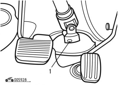
Figure 9.28. Removing the steering wheel shaft: 1 - bolt
- unscrew bolt 1 (figure 9.28) steering wheel shaft cardan joint;
- remove the steering cardan shaft (see the "Steering" section) by removing the protective retainer;
- disconnect the cable from the clutch pedal and remove it from the front shield;
- disconnect the vacuum hose;
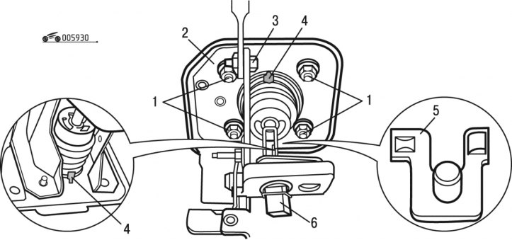
Figure 9.30. Removing the pedal assembly: 1 - nuts; 2 - pedal bracket; 3 - bolt; 4 - latches; 5 - axis; 6-pin connector
- unscrew bolt 3 (see figure 9.30);
- remove axle 5;
- disconnect the 6-pin connector of the brake light switch;
- having removed the latches 4, remove the bracket 2 of the pedal and move it to the side;
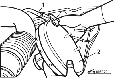
Figure 9.29. Removing the vacuum hose: 1 - vacuum hose; 2 - vacuum booster
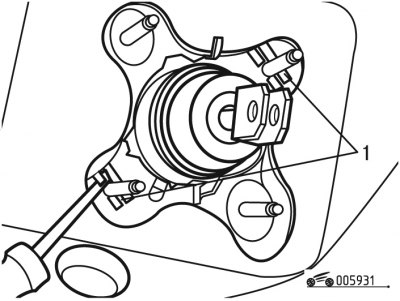
Figure 9.31. Removing the vacuum booster stud retainers: 1 - clamps
- remove the vacuum booster 2 through the engine compartment (figure 9.29), having previously removed the clamps 1 from the amplifier studs (figure 9.31);
- remove the gasket.
Install the brake booster in the following order:
- install a new gasket;
- replace axle 5 (see figure 9.30) and lubricate it;
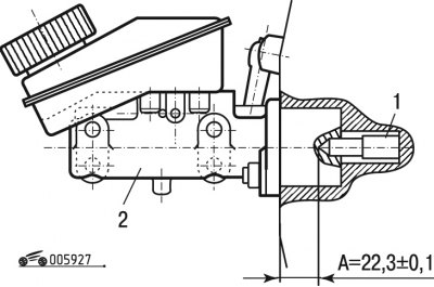
Figure 9.27. Installing the master brake cylinder: 1 - brake booster rod; 2 - master brake cylinder; A = (22, 3±0,1) mm
- check if the vacuum booster rod moves freely. Check that the distance A (see figure 9.27) between the head of the vacuum booster push rod and the mating surface of the master brake cylinder during installation was (22.3±0.1) mm. Otherwise, check the condition of the brake pedal;
- subsequent installation is carried out in the reverse order of removal, while the tightening torques of bolt 1 (see figure 9.28) — 25 Nm, 3 bolts (see figure 9.30) - 8 Nm, nuts 1 - 20 Nm.