Attention. Before proceeding with the repair of the gearbox, perform diagnostics by reading errors from the memory of the electronic engine control unit.
Note. For any damage or malfunction of the automatic transmission, check the oil level and quality.
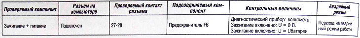
Error 1. Ignition + power
Pilot lamps «Sport» And «Snow» flashing: yes.
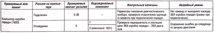
Mistake 2. Computer
Pilot lamps «Sport» And «Snow» flashing: yes.
Clear the error and make sure the error does not reappear, otherwise check with a new ECU.
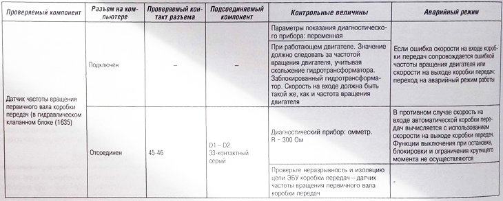
Error 3. Automatic transmission input speed (turbine speed)
Pilot lamps «Sport» And «Snow» flashing: yes.
The electronic control unit checks the consistency of information regarding the engine speed and speeds at the input and output of the gearbox.
If the gearbox input speed error is stored in memory, the gearbox output speed error is not stored.
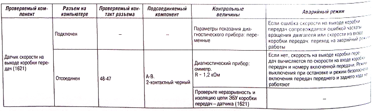
Error 4. Automatic transmission output speed (vehicle speed)
Pilot lamps «Sport» And «Snow» flashing: yes.
The ECU checks the consistency of information regarding engine speed and transmission input and output speeds.
If the vehicle speed error is stored in memory, then any possible gearbox input speed error will not be stored.
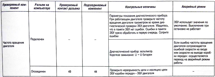
Error 5. Engine speed
Pilot lamps «Sport» And «Snow» flashing: yes.
The ECU checks the consistency of information regarding engine speed and transmission input and output speeds.
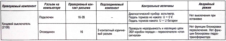
Mistake 6. Switch «brake lights»
Attention. There is only one switch.
Pilot lamps «Sport» And «Snow» flashing: no.
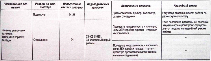
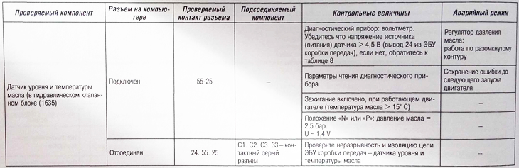
Error 7. Power supply for temperature and pressure sensors
Pilot lamps «Sport» And «Snow» flashing: no.
The following analog sensors are provided with a common voltage source distributed over individual connector pins:
- oil temperature sensor;
- oil level and temperature sensor.
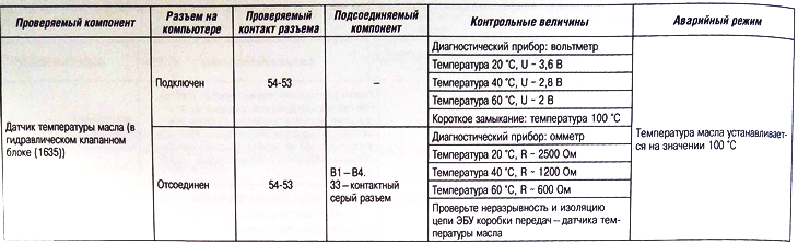
Mistake 8. Oil temperature
Pilot lamps «Sport» And «Snow» flashing: no.
Error 9. Oil pressure
Pilot lamps «Sport» And «Snow» flashing: yes.
The pressure sensor supplies the transmission ECU with a voltage proportional to the oil pressure.
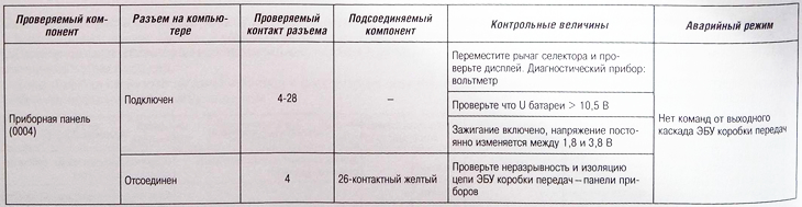
Error 10. Output to the dashboard (low speed signal)
Pilot lamps «Sport» And «Snow» flashing: yes.
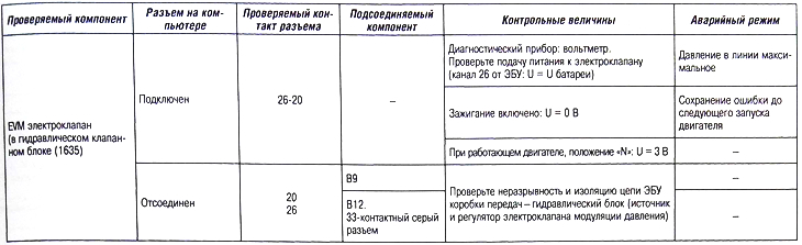
Error 11. Pressure modulation solenoid valve (EVM pressure)
Pilot lamps «Sport» And «Snow» flashing: yes.
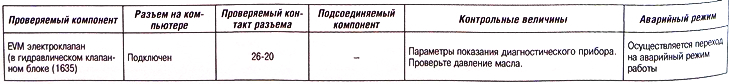
See the sequence of operations: the location of the solenoid valves in the hydraulic unit.
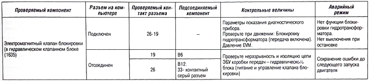
Error 12. Blocking solenoid valve (EVM shunt)
Pilot lamps «Sport» And «Snow» flashing: yes.
Note. See the sequence of operations: the location of the solenoid valves in the hydraulic unit.
Error 13. Torque limit
Pilot lamps «Sport» And «Snow» flashing: no.
Attention. Torque limitation does not occur if the oil temperature is less than a certain value. If the vehicle is equipped with a petrol engine, then torque limitation is performed by adjusting the ignition timing.
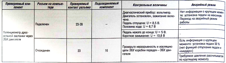
Error 14. Throttle potentiometer through the engine ECU
Pilot lamps «Sport» And «Snow» flashing: yes.
Errors in the engine ECU memory must be handled first.
Check if the error was present in the transmission ECU memory as intermittent.
If there are engine ECU errors, it informs the transmission ECU and the scan tool displays the message: «INJ throttle potentiometer error».
Otherwise, the scan tool displays the message: «Throttle Potentiometer Communication Error».
Error 15. Electrovalves 1-6
Pilot lamps «Sport» And «Snow» flashing: yes.
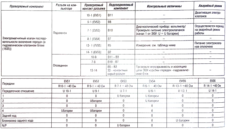
Note. See the sequence of operations: the location of the solenoid valves in the hydraulic unit.
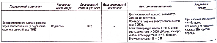
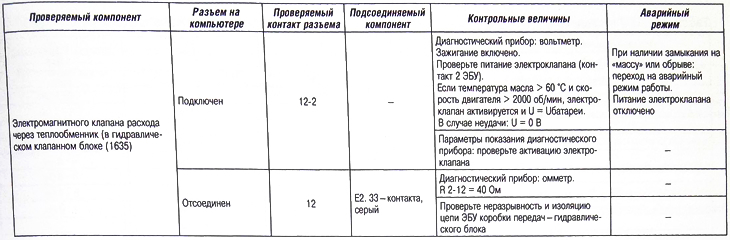
Error 16. Solenoid valve flow through the heat exchanger
Pilot lamps «Sport» And «Snow» flashing: yes.
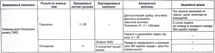
Error 17. Locking the selector lever
Pilot lamps «Sport» And «Snow» flashing: no.
Error 18. Multifunction switch
Pilot lamps «Sport» And «Snow» flashing:
- yes, in an unstable or prohibited position;
- No, in an intermediate position.
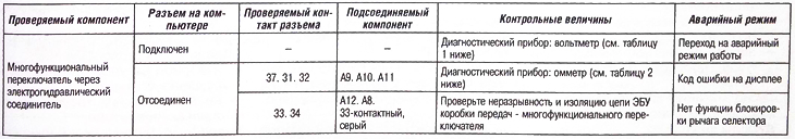
Table 1 (ECU connected)
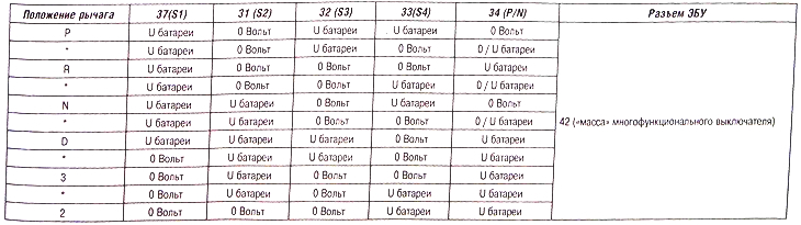
* Intermediate piece.
Table 1 (ECU connected)
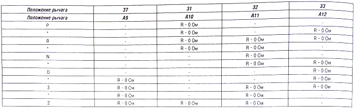
* Intermediate piece.
Check the continuity of the A4 circuit - «weight» body.
Check the continuity and insulation of circuit A8 (electro-hydraulic connector) — 34 (ECU automatic transmission).
Symptoms (pilot lamps «Sport» And «Snow» flashing)
Simultaneous flashing of signaling devices «Sport» And «Snow» means the following:
- overheating of the working fluid of the gearbox;
- aging and contamination of the working fluid;
- disconnection of the transmission ECU with the instrument panel;
- not done «education» accelerator pedals;
- computer is inactive (ECU is defective);
- request from diagnostic tool (check of executive devices).
Also, the flashing of signaling devices can be caused by a change in the following factors:
- oil pressure;
- throttle position (via potentiometer or engine ECU);
- gearbox input shaft speed;
- gearbox output shaft speed;
- engine speed;
- operation of the flow solenoid valve through the heat exchanger;
- operation of the pressure modulation solenoid valve;
- maximum pressure adjustment;
- the operation of the solenoid valve of the gear shift sequence;
- ECU operation or ECU power failure;
- operation of the multifunction switch.
Switchover delay
Switchover lag can be caused by a change in the following factors:
- gearbox input shaft speed;
- gearbox output speed;
- engine speed;
- torque smoothing;
- torque information from the electronic engine control unit.
Pressing the brake pedal does not disengage the lever lock in position «R»
The function of disabling the lock of the selector lever in position «R» does not work due to a malfunction:
- contact sensor of the brake system;
- lever lock relay.
Other malfunctions (fuel consumption, comfort, etc.)
Other malfunctions may be caused by:
- malfunction in the control of the solenoid valve for controlling the flow of the heat exchanger (short circuit «+»);
- failure in the control of the blocking modulation solenoid valve;
- faulty mode switch connection «kickdown»;
- information about the temperature of the transmission fluid.
Switching to emergency operation
Note. In this mode, only 3rd gear and reverse gear are available.
Clutch slip when starting. Emergency mode with the possibility of blocking the torque converter can be caused by a malfunction:
- solenoid valves for the gear shift sequence;
- throttle, if torque information is supported by the engine ECU;
- pressure modulation solenoid valve;
- multifunction switch;
- solenoid valve flow through the heat exchanger;
- incorrect adjustment of the main fluid pressure;
- not fulfillment «learning» accelerator pedal.
Emergency mode without torque converter lockup can be caused by:
- if the speed error at the input of the gearbox is accompanied by an error in the engine speed or speed at the output of the gearbox;
- if the speed error at the output of the gearbox is accompanied by an error in the engine speed or speed at the input of the gearbox;
- ECU for automatic transmission.
Teleloading
Updating Transmission ECU Program Using Remote Download: Follow the scan tool procedure.
Teledownload provides automatic transmission ECU software updates or adaptations to engine ECU modifications.
Before teleloading, it is necessary to record the readings of the working fluid wear counter available in the automatic transmission computer.
After downloading, you must:
- remove errors;
- perform initialization of the pedal;
- perform self-adaptation initialization;
- do programming (if necessary);
- enter the previously taken reading of the working fluid wear counter;
- perform road tests.
Note. Every time you update the automatic transmission ECU software, you must also update the engine ECU software.
Fluid Wear Meter Update
PROXIA station: access to reading and entering the readings of the fluid wear counter is provided through the menu: «Telecoding (button system) / working fluid wear counter». The fluid wear counter changes in increments of 2750.
LEXIA station - EL.IT block: access to reading and entering the readings of the working fluid wear counter is provided through the menu: «Working fluid wear counter».
Setting the readings of the working fluid wear counter is provided by directly entering the digits of the counter.
Telecoding
ECU Programming Procedure: Follow the scan tool procedure.
A new or newly programmed ECU is always configured with the following options:
- selector lever lock;
- without OBD output (emission reduction system L4).
If the ECU is intended for installation on a vehicle equipped with the L4 emission reduction system or not equipped with the selector lever lock system: carry out the programming operation.
Pedal initialization
Pedal initialization must be performed in the following cases:
- replacement of automatic transmission ECU;
- replacement of an automatic transmission;
- teleloading software to the ECU;
- replacement or adjustment of the accelerator pedal cable;
- throttle potentiometer replacement.
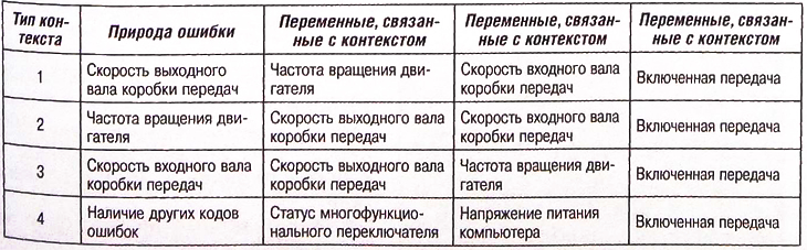
Error contexts
For each stored error, the following information is displayed:
- error type (temporary or permanent);
- error mode (short circuit or open circuit);
- three associated variables kept in memory when an error occurs.
There are four types of context. When multiple errors with the same type of associated context are stored in memory, only the context of the last error is displayed.
Context type table