



Table of contents: Removal 🠇 Installation 🠇
Removal
Raise and secure the vehicle on lifts.
Disconnect the battery.
Remove:
- front left wheel;
- front left fender liner;
- protection under the engine;
- protection under the front bumper.
Drain the automatic transmission oil (see the corresponding operation).
Remove the air filter unit. Remove the pipe (2) and support (3).
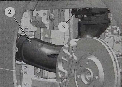
Disconnect the air pipes from the inlet and outlet of the heat exchanger.
Unscrew the bolt (4) and remove the heat exchanger (5) (see the corresponding operation).
Remove the 11 hydraulic unit housing mounting bolts (6).
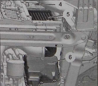
Note: The hydraulic block housing is installed on sealing paste.
Please note: The hydraulic unit housing contains approximately 0.5 l of oil.
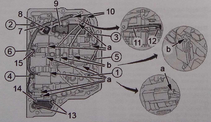
Disconnect the eight solenoid valve connectors (2) (in area "a") and the two speed sensor connectors (in area "b") using a thin screwdriver. Loosen the bolt (7) and remove the oil temperature sensor (8).
Unscrew the two bolts (13) and remove the cover (14).
Unfasten and move aside the wiring harness (10).
Note: The oil temperature sensor (8) is connected to the wiring harness (10).
Remove six bolts (15) (in sequence from 1 to 6).
Remove the hydraulic unit (9) by removing the rod (11).
Caution: Hold the manual valve (12) of the hydraulic connector (9) in place.
Handle all operations on the hydraulic unit with care and protect it from any contamination.
Installation
Install the hydraulic unit (9) into place by inserting the rod (11) into the gearshift drive.
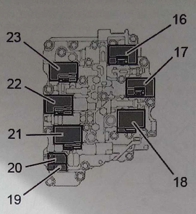
Location of electromagnetic valves in the hydraulic block:
16 - electromagnetic valve for modulating the torque converter lock-up pressure;
17 - electromagnetic valve for changing the clutch pressure "C3";
18 - electromagnetic valve of brake pressure modulation "B1";
19 - secant valve "S1"; 20 - secant valve "S2";
21 - electromagnetic valve for modulating pressure in the circuit;
22 - electromagnetic valve for changing the clutch pressure "C2";
23 - electromagnetic valve for changing the clutch pressure "C1".
Caution: Position the wiring harness (10) correctly in its fasteners and its socket (in area "c").
Do not pinch the speed sensor wire harnesses (24) and (25).
Install in place:
- six bolts (15) (tighten manually);
- lid (14) (with a new seal);
- two bolts (13) (tighten manually).
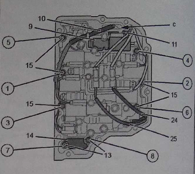
Tighten bolts (15) and (13) to 10 Nm (in sequence from 1 to 8).
Install the oil temperature sensor (8) and bolt (7) in place.
Connect the eight solenoid valve connectors (2) (in area "a") and the two speed sensor connectors (in area "b").
Caution: Check the positioning and fastening of the wiring harness (10).
Make sure the gear shift mechanism operates correctly in all positions.
Clean the surfaces to be joined.
Apply a layer of sealing paste to the hydraulic unit housing (6) (type "Loctite black tite").
Install the 11 hydraulic unit housing mounting bolts (6) and tighten to 15 Nm.
Connect the battery.
Replace and top up the automatic transmission fluid level (see the corresponding operation).
Update the oil wear counter using a scan tool.
Perform "training" of adaptation of electromagnetic valves and oil pressure regulators (in case of replacement of the hydraulic unit).
Install a heat exchanger (see the corresponding operation). Connect the air pipes to the inlet and outlet of the heat exchanger. Install the remaining parts in reverse order.