



Figure 148 shows a schematic diagram of the TU engine lubrication system. The figure shows the engine with a connection fitting for a pressure gauge. Figure 149 shows a diagram of the lubrication system of the XU10 engine (with a working volume of 2.0 liters). 8- and 16-valve engines have a similar design.
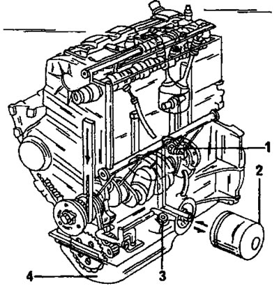
Figure 148. Lubrication circuit of the TU engine. 1. Oil pressure warning light switch; 2. Oil filter; 3. Oil pressure gauge sensor; 4. Oil pan
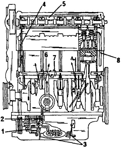
Figure 149. Lubrication circuit of the XU10 engine. 1. Oil pan; 2. Bypass valve; 3. Oil drain shield; 4. Cylinder head filter; 5. Oil pipeline; 6. Oil pressure switch; 7. Oil pressure sensor; 8. Return channel of the lubrication system
View the original on the website PeugeotBook.ru