



3.1.1. Removal and installation
Due to differences in operation, they are described separately for different types of engines.
TU type engines
The oil pump can be removed without removing the engine.
- Raise the front of the vehicle or, if possible, drive it onto an overpass or place the front wheels on a lifting ramp.
- Place a suitable container under the oil pan and drain the oil from the engine. The oil should be at least warm so that it drains better.
- Unscrew the muffler pipe from the connecting flange of the exhaust manifold and release the pipe from the rear side from the mount on the drive gearbox.
- Loosen the oil pan mounting bolts around the circumference and lower the oil pan down. Carefully tap the stuck oil pan with a rubber hammer; do not insert a screwdriver between the contact surfaces.
- Using Figure 150, unscrew the three oil pump mounting bolts and remove the pump from the cylinder block. To do this, you have to tilt the pump slightly to loosen the chain tension and release it from engagement with the pump sprocket. After this, the pump can be pulled out. The chain remains hanging.
If the oil pump is removed due to low oil pressure, it is best to install a new oil pump, as the pump housing and gears are most likely worn out.
If necessary, disassemble the oil pump as follows. In the description, references are made to the digital designations of Figure 151.
- Unscrew the oil intake screen (2) from the pump body (1) and separate the two parts.
- Remove the parts shown in the figure from inside the pump body.
- Check the oil pump gears carefully. The gear (5) can be removed from the shaft from the inside of the pump body. The other gear cannot be removed. If increased wear is detected on one of the gears, the other gear must also be replaced, since otherwise it will also be subject to increased wear.
- Check the integrity and absence of wear of the bypass piston and piston spring. Replace parts if necessary.
The oil pump is assembled in reverse order. Generously lubricate the inside of the pump with engine oil and install the oil pickup screen. The bolts are tightened to a torque of 7 Nm.
Before installing the oil pump, thoroughly clean the contact surfaces of the crankcase without using sharp objects. Check the presence of the centering sleeve in the location shown in Figure 152 on the cylinder block.
Install the oil pump while engaging it with the drive shaft. To do this, tilt the pump slightly again to place the chain on the sprocket, and then place the pump on the centering sleeve. Install the three mounting bolts and tighten them evenly to a tightening torque of 8 Nm.
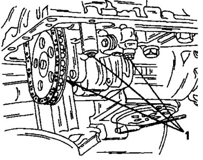
Figure 150. Mounting bolts (1) on the bottom side of the engine crankcase.
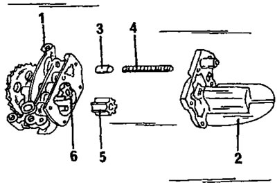
Figure 151. Oil pump parts. 1. Oil pump housing; 2. Oil intake mesh; 3. Bypass piston; 4. Piston spring; 5. Removable gear; 6. Rigidly fixed gear
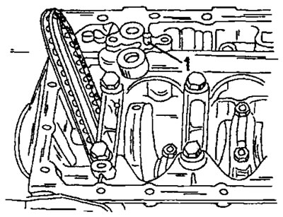
Figure 152. Location of the centering sleeve (1) in the engine crankcase. For clarity, the engine is shown with the crankcase open.
Cover the contact surface of the oil pan with sealing compound and install the pan. Tighten the 19 bolts evenly around the circumference to a torque of 8 Nm.
Install the muffler pipe with a new gasket and secure the end of the pipe to the drive gearbox. Tighten the connection to the manifold with a torque of 30 Nm, and the fastening on the gearbox with a torque of 45 Nm.
Check if the oil drain plug is tightened (tightening torque 30 Nm) and pour the prescribed amount of oil into the engine. Disconnect the high tension wire in the middle of the ignition distributor. Turn the engine over with the starter until the oil pressure warning light goes out. This ensures that the pressure generated by the oil pump is sufficient to lubricate the engine. After this, reconnect the wire.
Start the engine and let it run for a while. Carefully check the oil pan for leaks. Also, after some mileage, check the oil level again and, if necessary, add oil to the engine to correct the oil level.
XU-type engines
The oil pump is removed with the engine removed after the oil sump has been removed. The pump is removed in the same manner as described when disassembling the engine. Oil pump assembly is similar to that on other engine types and is performed in the manner described for the TU engine. Gear clearances are measured using Figure 153. Clearances "A" between the edges of the gears and the pump housing and axial clearance "B" of the gears are measured.
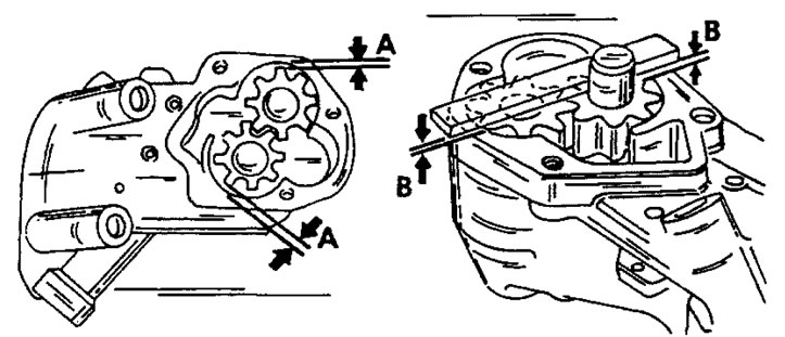
Figure 153. The clearance between the outer edge of the gears and the pump body is measured at location "A", and the axial play at location "B".
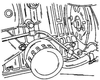
Figure 154