



Table of contents: On all engines: 🠇 Engines with a displacement of 1.4…🠇 XU-type engines 🠇 All engines except 16-valve and…🠇 Turbodiesel and 16-valve engines 🠇
The gearbox is installed in the reverse order, however the following points should be taken into account depending on the engine installed:
On all engines:
- Regardless of whether work has been carried out on the gearbox or not, it is imperative to replace the drive shaft seals on the sides of the gearbox.
- Replace the oil filler and drain plug seals.
- Replace all self-locking nuts and washers, the latter if their appearance is unsatisfactory.
The gearbox is installed in the following sequence:
Engines with a displacement of 1.4 and 1.6 liters
- Lubricate the sealing lips of the drive shaft oil seals with universal grease and attach the oil seals to the holes. Using a punch or a pipe of the appropriate diameter, press in the seals until their outer surfaces are recessed. Be careful not to damage the seals.
- Lubricate the splined portion of the clutch shaft, the guide sleeve of the clutch release bearing and the pin of the clutch release fork with graphite grease, for example Molykote BR2. Check for the presence of centering pins on the mating surface of the gearbox. Using a piece of string or wire, pull the clutch release fork back until the release bearing rests on the stop.
- Place the gearbox under the vehicle and secure the cable or chain to the gearbox eye. Raise the gearbox on a lifting mechanism until it is approximately opposite the engine.
- Press the gearbox towards the engine and simultaneously engage the clutch shaft with the driven clutch disc. If the shaft does not engage immediately, have an assistant turn the engine in different directions using the V-belt until the gearbox shaft enters the disc. In most cases, a slight twist is enough to engage.
- Press the gearbox completely against the engine so that there is no gap. Insert three bolts from the top side connecting the gearbox to the engine and tighten them to a torque of 35 Nm.
- Slowly raise the engine with the gearbox so that the gearbox mount can be installed, while maintaining the following tightening torques:
The support journal is tightened on the gearbox with a torque of 20 Nm.
The rubber-metal support is attached to the body with a tightening torque of 25 Nm.
- Tighten the nut in the middle to a torque of 65 Nm.
- Tighten the lower gearbox-to-engine connection bolt to a torque of 45 Nm.
- Connect the gear shift rods to the side of the gearbox.
- Install the drive shafts in accordance with the instructions in section 9.1.
- Tighten both nuts (1) in Figure 190 to a torque of 18 Nm. The bolts should be returned to their original position by turning them back half a turn.
- Insert the ball joint pin from the bottom of the steering knuckle. Apply a protective washer first. Press the transverse arm all the way up and insert the bolt into the tension spline (1) in Figure 193. Screw the nut on the other side and tighten the connection to a torque of 45 Nm. Perform the work on both sides of the vehicle.
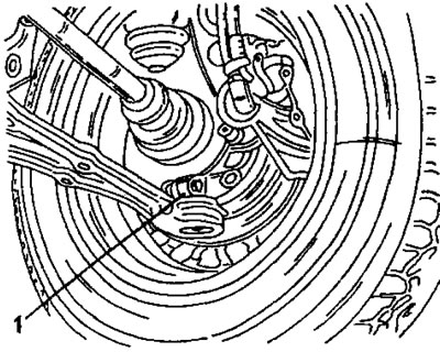
Figure 193. Connecting the lower control arm. Insert the ball pin into the slot (1).
- Install the starter together with the air filter mount. Tighten the three bolts to 18 Nm.
- Restore the following connections: connect the speedometer flexible shaft, connect the clutch cable and adjust the clutch pedal, connect the gearbox ground jumper, connect the reverse light switch wire.
- Install the air filter, battery tray, battery, ABS control unit, etc.
- Fill the gearbox with oil. Check again that the oil drain plug is tightened. Close the oil filler plug.
- Lower the vehicle onto its wheels and tighten the nuts on both drive shafts to a torque of 265 Nm. Apply the handbrake firmly. Tighten the wheel bolts and install the decorative caps on the wheels.
- Take a test drive and check that all gears engage easily.
XU-type engines
Here it is necessary to pay attention to the design differences of the clutch release mechanism. Turbodiesel and 16-valve engines have pull-type clutch release mechanisms. On all other engines, pressure is applied to the release bearing.
All engines except 16-valve and turbodiesel
- Lubricate the sealing lips of the drive shaft oil seals with universal grease and attach the oil seals to the holes. Using a punch or a pipe of the appropriate diameter, press in the seals until their outer surfaces are recessed. Be careful not to damage the seals.
- Lubricate the splined portion of the clutch shaft, the clutch release bearing guide sleeve, and the clutch release fork pin with graphite grease, such as Molykote BR2. Check for the presence of centering pins on the mating surface of the gearbox. Using a piece of string or wire, pull the clutch release fork back until the release bearing rests on the stop.
Turbodiesel and 16-valve engines
Place the release bearing onto the clutch as shown in Figure 194.
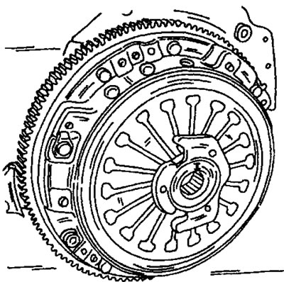
Figure 194. The clutch release bearing must be installed as shown with the notches facing forward.
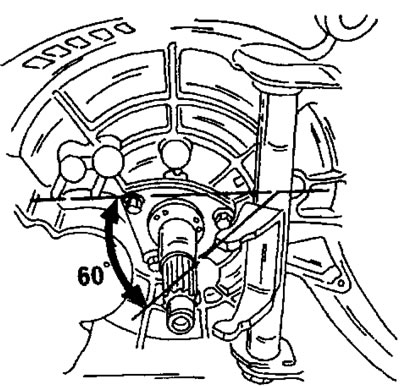
Figure 195. When connecting the gearbox, set the clutch release fork at the specified angle. By installing the rod into the hole in the axle (1) in Figure 196, the axle can be locked in this position by engaging the gearbox.
- Rotate the clutch release fork shaft until the ends of the fork are at 60° to the mating surface of the clutch basket. This position of the fork is necessary for proper engagement of the clutch release fork. When connecting the gearbox to the engine, the ends of the fork should go behind the release bearing. Therefore, first check the position of the fork once again to ensure it matches Figure 195.
- Place the gearbox under the vehicle and secure the cable or chain to the gearbox eye. Raise the gearbox on a lifting mechanism until it is approximately opposite the engine.
- Press the gearbox against the engine and simultaneously engage the clutch shaft with the driven clutch disc. If the shaft does not engage immediately, have an assistant turn the engine in different directions using the V-belt until the gearbox shaft enters the disc. In most cases, a slight twist is enough to engage.
- Press the gearbox completely against the engine so that there is no gap. Insert three bolts from the top side connecting the gearbox to the engine and tighten them to a torque of 45 Nm.
- On a 16-valve or turbodiesel engine, observe the end of the protruding clutch release shaft. After inserting the rod, move the axis (1) in Figure 196 in different directions. In this case, a slight play should be felt, that is, the clutch release fork is installed behind the release bearing. The hole for the tie bolt must be located parallel to the connecting surface of the clutch basket, as shown in Figure 196.
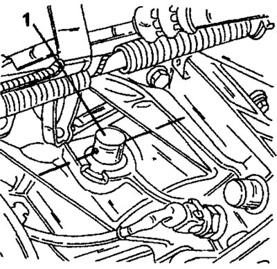
Figure 196. The hole for the tie bolt should be located parallel to the connecting surface of the clutch basket.
Note: Before performing the following steps when connecting the gearbox, be sure to ensure that the clutch release fork and release bearing are correctly installed.
(Information copied from the resource: PeugeotBook.ru)
Slowly raise the engine with the gearbox so that the gearbox mount can be installed, while maintaining the following tightening torques (Figure 191):
- The support journal (4) is tightened onto the gearbox with a torque of 50 Nm. Lubricate the journal threads with Loctite.
- Tighten the bolts (3) to a torque of 25 Nm.
- Tighten the nut (2) to a torque of 65 Nm.
- Tighten the bolts connecting the gearbox to the engine from the bottom and tighten them to a torque of 45 Nm.
- Connect the gear shift rods to the side of the gearbox.
- Install the drive shafts in accordance with the instructions in section 9.1.
- Tighten both nuts (1) in Figure 190 to a torque of 18 Nm. The bolts should be returned to their original position by turning them back half a turn.
- Insert the ball joint pin from the bottom of the steering knuckle. Apply a protective washer first. Press the transverse arm all the way up and insert the bolt into the tension spline (1) in Figure 193. Screw the nut on the other side and tighten the connection to a torque of 45 Nm. Perform the work on both sides of the vehicle.
- Install the starter. Tighten the three bolts to 20 Nm.
- Restore the following connections: connect the speedometer flexible shaft, connect the clutch cable, connect the gearbox ground jumper, connect the reverse light switch wire.
- Install the air filter, battery pan, battery, ABS control unit, etc. Don't forget that on a 16-valve engine, you need to add coolant.
- Fill the gearbox with oil. Check again that the oil drain plug is tightened. Close the oil filler plug.
- Lower the vehicle onto its wheels and tighten the nuts of both drive shafts to a tightening torque of 265 Nm with a thread diameter of 20 Nm (m20 thread) or a tightening torque of 320 Nm with a thread diameter of 24 Nm (m24 thread). At the same time, tighten the handbrake firmly. Tighten the wheel bolts and install the decorative caps on the wheels. The tightening torque of wheel bolts is 85 Nm.