



Mark the position of the clutch relative to the flywheel in case the clutch needs to be reinstalled. To do this, a punch is used, which is used to strike the clutch and flywheel.
Loosen the six clutch bolts evenly and crosswise until the springs are relieved. At the same time, you should hold the flywheel from turning.
Remove the clutch and pull out the driven disc. The engine will then look as shown in Figure 176. If the clutch gets stuck on the flywheel pins (2), you can use a screwdriver to carefully push the clutch away from the flywheel. Note that the longer side of the driven disk hub faces the gearbox, i.e. outward. This should be remembered and taken into account during installation.
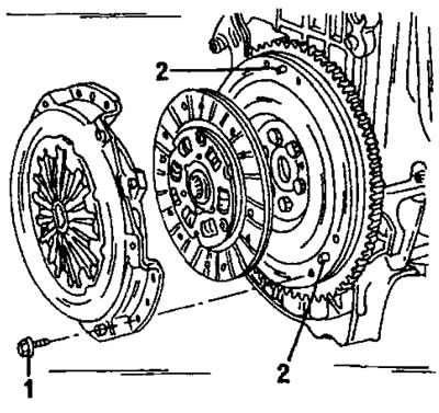
Figure 176. Removing the clutch and driven disc. Bolts (1) on TU type engines are tightened to a torque of 15 Nm, and on XU type engines to a torque of 20 Nm. Centering pins (2) enter the holes in the clutch drive disc.
Immediately wipe the inside of the flywheel with a rag and check its working surface. If the driven disk is worn down to the rivet heads, it is possible that the rivets have damaged the flywheel surface or the drive disk.
[You can find the original on the page: peugeotbook.ru]
In cases where it is necessary to separate the engine and gearbox, it is necessary to remove the clutch to check it. If the flywheel running surface does not appear to be in perfect condition, you should take this opportunity to remove the flywheel for resurfacing. In this case, the maximum thickness of material removal allowed is 0.5 mm. To maintain clamping force, the same thickness should be removed from the adjacent clutch surface.