
- turn off the ignition and disconnect the wire «masses» from the storage battery;
Note. The automatic transmission is sealed, so it is not necessary to drain the oil when removing and installing it.
- the gearbox is removed upwards from the engine compartment;
- put the car on a lift;
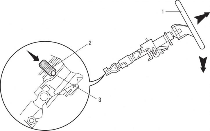
Pic. 5.49. Removing the steering column (the direction of movement is indicated by arrows): 1 - steering column; 2 - button; 3 - pointer of the universal joint of the steering shaft
- install steering wheel 2 (pic. 5.49) to the lowest position and move as far back as possible;
- remove the subframe;
- press button 1 on the index of the cardan joint 3 of the steering shaft to fix the steering column in a fixed position;
- unscrew the nut of the left axle shaft;
- lift the car;
- remove the exhaust system;
- secure the steering box to the panel using the bracket;
- remove the left half shaft;
- disconnect the inner hinge of the right axle shaft from the gearbox and, using a soft wire, hang it to the body;
Pic. 5.50. Removing the electrical connector: 1 - plates; 2 - bolts; 3 - electrical connector; 4 - nuts
- unscrew bolts 1, nuts 3 (pic. 5.50);
Attention! When removing the exhaust system, it is necessary to protect the connecting element in the front exhaust pipe from any mechanical damage and contact with any corrosive products. The connector in the front exhaust pipe must not be bent by more than 20°in the angle of rotation or misaligned by 20 mm axially and 25 mm radially, otherwise it will be damaged. After servicing and repairing the exhaust system, check that the system is installed freely, without stress, with sufficient clearance relative to the body elements.
- disconnect an electric socket 2;
- remove plate 4 covering the drive hole;
- remove the speed sensor;
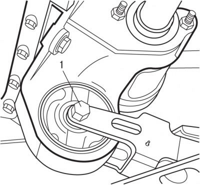
Pic. 5.51. Support bolt location (1)
- unscrew the nut, remove the bolt and remove the support 1 (pic. 5.51);
- unscrew the starter mounting bolts, take it aside along with the wires and fix it with soft wire on the body;
- remove the shock-proof amplifier of the sub-frame;
- turn out the lower bolts of fastening of a transmission to the engine;
- lower the car;
- disconnect the pipes from the air filter;
- remove the air filter;
- remove the resonator;
- remove the decorative battery cover;
- remove the mudguard of the left front wheel arch;
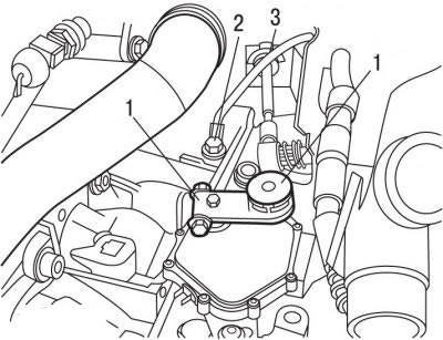
Pic. 5.52. Ball head location: 1 - ball tip; 2 - bolt; 3 - cable stop
- from under the arch of the left front wheel, unscrew the bolt 1 (pic. 5.52) fastening of a support of the accumulator battery;
- remove the battery;
- remove the battery support;
- unscrew bolt 2;
- using the tool for removing the ball bearings, remove the ball end 1 of the cable;
- use a screwdriver blade to remove stop 3 of the cable sheath;
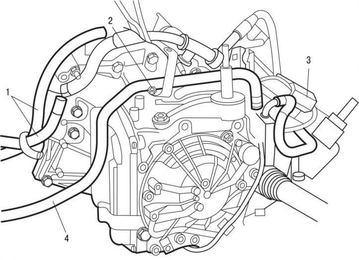
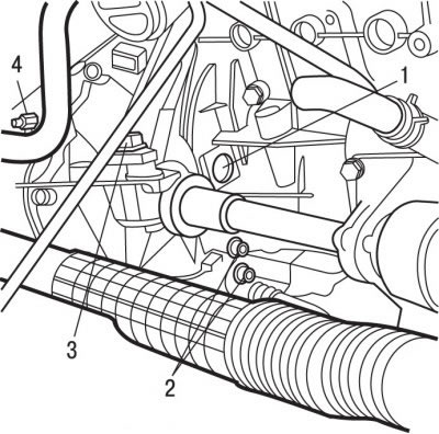
Pic. 5.53. Hoses location: 1, 4 - hoses; 2 - support; 3 - connecting nut
- clamp hoses 1 and 4 with special clamps (pic. 5.53);
- turn out bolts of fastening of a support 2;
- loosen the clamps and remove the hoses 1 from the fittings;
- release from clips and take aside from a transmission plaits of wires;
- unscrew the connecting nut 3;
- install support bar 0009 to support the power unit;
- hook the catch of the support cross member to the bracket to lift the engine;
- hook the hooks of the cable of the lifting mechanism to the gearbox;
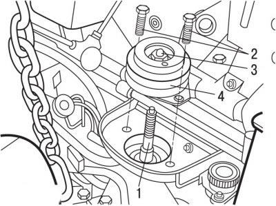
Pic. 5.54. Fastening elements of the elastic support: 1 - axis; 2 - bolts; 3 - nut; 4 - elastic support
- unscrew nut 3 (pic. 5.54) fixing the elastic support and remove it together with the washer;
- turn out bolts 2 fastenings of an elastic support;
- remove the elastic support 4;
- using a special bushing 0317-AB, remove the gearbox suspension axle;
- while supporting the gearbox, unscrew the upper bolts securing the gearbox to the engine;
- shift the gearbox away from the engine and remove from the guide pins. After sufficient clearance is formed, fix the torque converter to the gearbox with tool 0338-D or 0338-S;
- carefully remove the gearbox.
Installation is carried out in the reverse order of removal, taking into account the following:
- when installing the gearbox, it is necessary to replace it with new self-locking nuts and bolts, as well as sealing rings and gaskets;
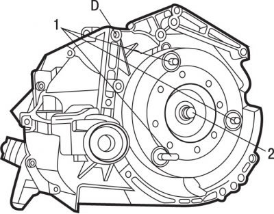
Pic. 5.55. Location of fastening elements for gearbox 0338-A with TU3JP and TU5JP4 engines: 1 - centering pins; 2 - supply pin; D - the place where MOLYCOTE BR2 grease is applied to the front cone of the gearbox
- during installation, check the presence of centering pins 1 (pic. 5.55) or 3 (pic. 5.56), determining the relative position of the engine and gearbox;
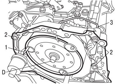
Pic. 5.56. Location of fastening elements for gearbox 0338-A with EW10J4 engine: 1 - supply pin; 2 - centering pins; 3 - hairpins; D - the place where MOLYCOTE BR2 grease is applied to the front cone of the gearbox
- install pin 2 on the gearbox torque converter (see fig. 5.55) or 1 (see fig. 5.56) for the supply of gearbox 0338-A;
- remove tool 0338-D or 0338-S holding the torque converter to the gearbox;
- on the gearbox installed with the EW10J4 engine, remove the pin 3 (see fig. 5.56), holding the torque converter;
- apply MOLYCOTE BR2 grease to the torque converter front cone D (see fig. 5.55, 5.56);
- align the pin 0338-A for connecting the gearbox to the driving plate 4 (see fig. 5.50);
Attention! When installing the gearbox, be careful not to deform the plate.
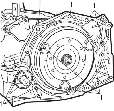
Pic. 5.57. Bolt location (1) gearboxes and nuts (2) torque converter mounts
- screw in the top bolts 2 (pic. 5.57) fastening the gearbox to the engine and tighten them with a torque of 52 Nm;
- remove the fixture holding the torque converter;
- screw bolts 3 fastening the gearbox to the engine;
- remove the pin 0338-A to bring the gearbox to the plate;
- screw in the lower bolts 1 for fastening the gearbox to the engine and tighten them to a torque of 52 Nm;
- screw nuts 4 fastenings of the hydrotransformer. Tighten the nuts one by one to 10 Nm, then tighten them in the same sequence to 30 Nm. Make sure there is no gap across the entire mating surface;
- apply to axle thread 1 (see fig. 5.54) gearbox suspension LOCTITE FRENETANCH locking compound preventing its self-unscrewing;
- screw in the gearbox suspension axle with a washer and tighten it to 50 Nm;
- install an elastic pillow of a suspension bracket of a transmission;
- screw in bolts of fastening of an elastic pillow of a suspension bracket of a transmission, having tightened them at this stage by hand;
Attention! Before tightening the elastic mount bolts, center the position of the power unit.
- install the washer and tighten the nut 3 of the gearbox suspension axle;
- tighten bolts 2 to 30 Nm, and nut 3 to 65 Nm;
- further installation is carried out in the reverse order of removal, taking into account the following;
- install drive shafts;
- install the subframe;
- check the oil level in the gearbox;
- check the coolant level;
Attention! In the event of an AL4 gearbox replacement, update the oil aging counter database using the DIAG 2000 diagnostic tool.
- connect wire «masses» to the battery;
- initialize all computers;
- perform the accelerator pedal position learning process.