



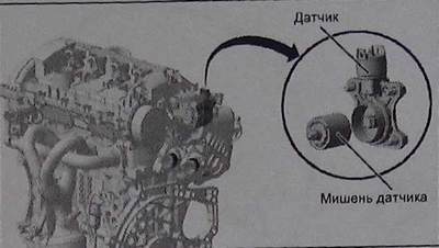
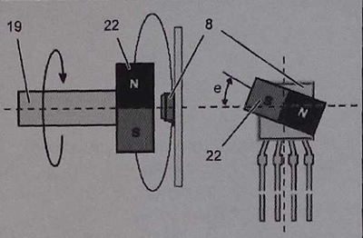
Operation diagram of the intake valve position sensor:
8 - valve position sensor;
19 - camshaft;
22 - sensor target;
e - angle of intermediate position of the camshaft.
A target (22) with a permanent magnet is installed at the end of the camshaft (19). The valve position sensor (8) transmits two signals under the influence of the magnetic field of the target. The first signal determines the value of the angle "e", which is from 0° to 180°, the second signal is a confirmation, showing the angle from 180° to 0°.
The engine control unit uses the information about the intermediate camshaft angle (19) to determine the amount of lift of the intake valves.
If the valve position sensor is damaged, the engine ECU sets the valves to maximum lift and controls the air supply through the electric throttle body.