
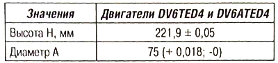
Cylinder block
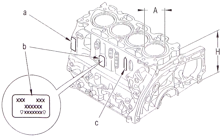
Marking «A»:
- engraving of the diameter class of the crankshaft bearings;
- orientation of the bearings to the clutch and to the timing drive.
Marking «b»:
- manufacturer's mark;
- type of internal combustion engine;
- node label;
- serial number.
Marking «With»:
- processing marking;
- year of issue.
Attention. It is forbidden to grind the plane of the block, which is joined with the cylinder head gasket. It is also forbidden to bore the cylinder bores.
The cylinder block is made of aluminum alloy, die cast together with cast iron liners. The main bearing covers are made of cast iron and are integrated into the crankcase during casting of the main bearing covers.
The crankshaft main bearing bed housing is fastened with 10 M9 bolts on each side of the bed, the cut line is closed with 14 Mb bolts.
Moving engine parts
The crankshaft is steel, stamped, with main and connecting rod journals having fillets, hardened by knurling with a ball, and integrated counterweights.
The tightness of the ends of the crankshaft is ensured by oil seals in the cylinder block on the flywheel side and in the oil pump housing on the timing drive side. Connecting rods - steel, stamped, with a bolted cover and a broken lower head with smooth liners.
Inserts on the side of the main bearing beds - without fixing protrusions, liners on the side of the cylinder block with fixing protrusions.
The piston is made of aluminum alloy with an oil cooling chamber. Piston Ring - Double Trapezoidal Clamped Type (№ 1).
Oil scraper ring - with scraper edges (№ 2).
Piston ring - I-section, tapered, chrome plated (№ 3).
Note. When assembling, make sure that the parts to be installed are correctly oriented.
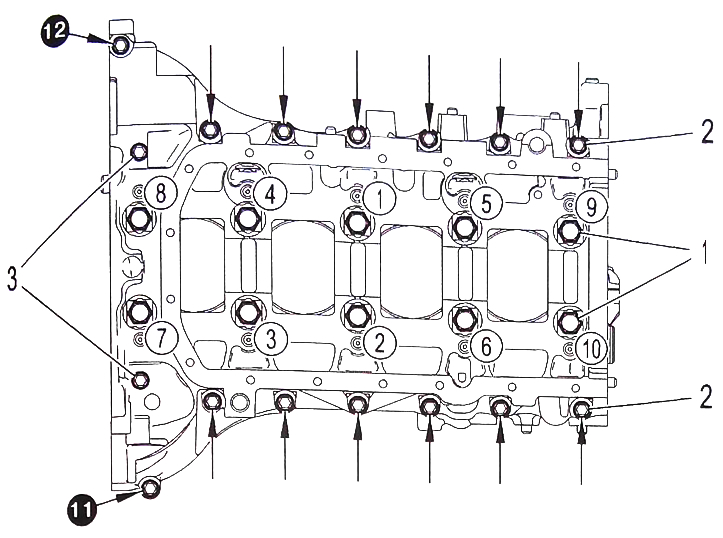
Tightening torques (crankcase main bearing caps)
Attention. Tightening must be carried out in the specified sequence.
Reuse of bolts (1) fastening of main bearing caps is prohibited.
Maximum bolt length 116.5 mm. Stage 1:
- pre-tighten new bolts (1) covers of main journals with a torque of 10 Nm (1 to 10);
- pre-tighten 14 bolts (2) fastening of the crankcase covers of the main bearings of the crankshaft with a torque of 6 Nm (1 to 14);
- tighten two bolts (3) torque 8 Nm (inside the flywheel housing);
- tighten two bolts (7) fastening the crankcase covers of the main bearings of the crankshaft with a torque of 8 Nm.
Step 2: Loosen the bolts (1) 180°.
Step 3: Tighten the bolts (1) neck cover crankcase torque 30 Nm (1 to 10).
Stage 4:
- tighten the bolts (1) with 140°angle (from 1 to 10);
- tighten the bolts (2) torque 0 Nm (1 to 14).
Attention. Tightening must be carried out in the specified sequence.
Reuse of bolts (5) connecting rod caps are prohibited.
The maximum length of the bolt under the head is 41 mm.
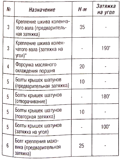
* When the required angle is reached, the tightening torque must be between 8 and 16 Nm.
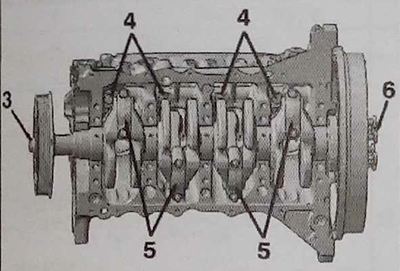
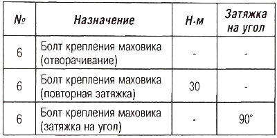
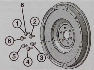
Tightening torques (flywheel)
Attention. Tightening must be carried out in the specified sequence.
Reuse of bolts (6) flywheel mounting is prohibited. The maximum bolt length is 16.2 mm.
Note. When installing, adjust the position of the engine flywheel on the crankshaft.
Tightening sequence:
- pre-tightening the bolts with a torque of 25 Nm (order 1-5-32-6-4);
- loosening the bolts in the order 1-5-3-2-6-4;
- bolt pre-tightening torque 8 Nm (order 1-5-32-6-4);
- tightening torque 30 Nm (order 1-5-3-2-6-4);
- additional tightening by 90° (order 1-5-3-2-6-4).