Table of contents: Boost Pressure Check Data 🠇 Checking the air supply circuit 🠇
Disconnect the connector at ion "a". Loosen the screw (2) and remove the boost pressure sensor (1).
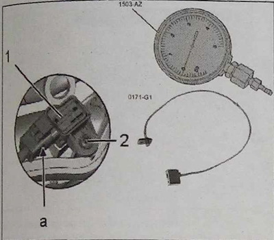
Attach the 0171-G1 intake manifold pressure/vacuum control gauge to the location of the boost air pressure sensor and secure it with the screw (2).
Connect the boost pressure sensor (1) to tool 0171-G1.
Connect the 1503-AZ boost pressure gauge to the 0171-G1 tool.
Connect the connector to the boost pressure sensor (1) in area "a".
Connect the diagnostic tool to the vehicle diagnostic connector.
Turn on the diagnostic tool in the parameter measurement mode. Start the engine.
Measure turbo boost pressure using the 1503-AZ boost pressure gauge (see table at the end of the chapter).
Note: If there is a large difference between the pressure readings from the diabetes device and the pressure gauge, replace the boost pressure sensor.
If the measured pressure in the system is below the standard value, check the following components:
- turbocharger inlet and outlet air ducts;
- air ducts at the inlet and outlet of the charge air cooler;
- charge air cooler;
- turbocharger.
If the measured pressure in the system (maximum 1 bar) above the standard value, check the turbocharger control system.
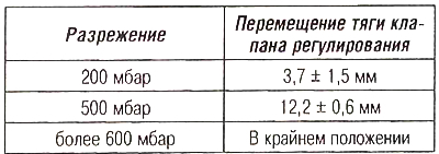
Boost Pressure Check Data
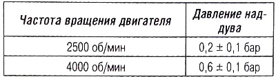
Checking the air supply circuit
Vacuum pump: The voltage value should be 0.9 ±0.1 Ohm at idle.
Boost pressure control valve (engine DV6ATED4)
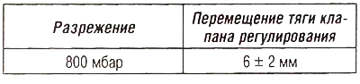
Boost pressure control valve (dV6TED4 engine)