



The high pressure fuel pump cannot be repaired or overhauled. If the pump is not functioning properly, it must be replaced. Roto-Diesel (Lucas-CAV) or Bosch high-pressure fuel pumps are installed.
Adjustment, as well as removal and installation of the high-pressure fuel pump, require special tools and should not be attempted without such tools. Below is a description of the work that can only be performed with a special tool.
Diesel engines operate either with direct injection or with fuel injection into the intake manifold or pre-chamber. In a Peugeot diesel engine, fuel is injected into a pre-chamber in the cylinder head, connected to the main combustion chamber. Fuel combustion begins in the pre-combustion chamber and, under the influence of increasing pressure, burning fuel particles enter the main combustion chamber, where they are completely burned.
With the development of diesel engines, there have been some innovations that deserve a brief mention.
Fuel filter and fuel heater: Fuel filtration and heating are functions of the engine. The fuel is heated by the coolant flowing through the 8 channels of the cooling system. The thermostatic element shown in Figure 402 regulates the amount of fuel heated. The degree of heating depends on the ambient temperature. At temperatures below 15°C, the thermostatic element moves from its position "a." Fuel can then enter through port "c," flow through port "d," be heated by the water nipple, and then flow to the filter through ports "e" and "b." As the temperature rises to between 15°C and 35°C, the thermostat valve is not fully open. In this case, only part of the fuel enters the filter through the described path. The remaining fuel is fed into the filter directly through "c" to "b".
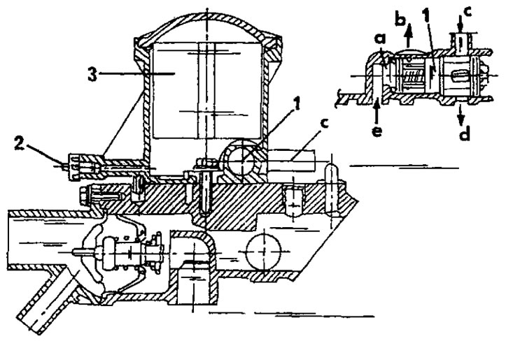
Figure 402. Sectional view of fuel filter and fuel heating device. References to letter designations are given in the text. 1. Thermostatic element; 2. Air bleed valve; 3. Fuel filter
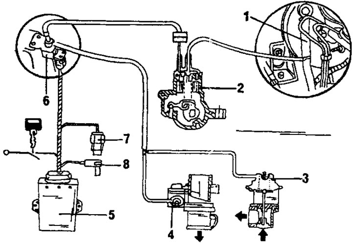
Figure 403. Schematic diagram of the exhaust gas recirculation (EGR) system. 1. Brake booster hose; 2. Vacuum converter; 3. EGR valve; 4. Flow valve; 5. Electronic control unit; 6. Solenoid valve; 7. Coolant temperature sensor; 8. Engine speed sensor
The power circuit has an automatic air removal device. For this purpose, an air bleed valve is installed.
Exhaust Gas Recirculation (EGR) System: This system is installed on vehicles equipped with a catalytic converter. The system reduces emissions of harmful substances into the atmosphere by diverting part of the exhaust gases back into the air intake system. Exhaust gas recirculation occurs under certain conditions, that is, depending on the engine coolant temperature, engine speed and the position of the gas pedal. From two temperature sensors (7) and speed sensors (8), information is sent to the electronic control unit (5) to regulate the recirculation process. Exhaust gas recirculation occurs when the engine temperature is above 48°C and its speed is between 1500 and 2000 rpm. The control unit opens the solenoid valve (6), which controls the entire system. The vacuum removed from the brake booster acts on the EGR valve (3) and the flow valve on the throttle body (4), which ensures combustion of the exhaust gases.
The highest vacuum is achieved at low speeds. The EGR valve is open, allowing exhaust gases to enter the intake manifold pipe. The circulation of exhaust gases is maintained by the pressure difference in the intake manifold pipe and in the exhaust manifold, which is determined by the position of the flow valve in the throttle body, that is, this valve is almost closed.
As soon as the engine speed increases, the working vacuum decreases and, under the influence of the return spring, the EGR valve closes, and the supply of exhaust gases to the intake system stops. At the same time, the throttle valve opens, so that the amount of air sucked in increases.
Speed sensor: It is installed in the engine crankcase and sends a signal to the electronic control unit when the engine speed is between 1500 and 2000 rpm, which causes exhaust gas recirculation.
Coolant Temperature Switch: The switch is located in the outlet fitting of the cooling system (A, Figure 397) and provides information to the electronic control unit at temperatures above 48°C, which causes exhaust gas recirculation.
Solenoid Valve: The valve is controlled by the ECU and regulates the flow of exhaust gases to the EGR valve and to the flow valve in the throttle body.
EGR valve: The EGR valve is installed on the intake manifold and regulates the removal of exhaust gases. The control vacuum acts on the upper chamber of the valve. This causes the membrane to move, which causes the valve to partially or completely open and exhaust gases to be discharged into the intake manifold pipe. In the absence of vacuum, the valve is held in its position by a spring.
Flow control valve: located in the throttle body and works in conjunction with the EGR valve. The valve is controlled by a vacuum box, which operates in the opposite direction to the EGR valve; when the valve is closed, the throttle valve is open. The valve has two functions:
It regulates the ratio of air and exhaust gases.
At idle or low load, the valve is fully open. When the throttle valve is almost closed, a pressure difference is created which accelerates the flow of exhaust gases to the intake manifold pipe. The high-pressure fuel pump has a vacuum converter (2). It is controlled by rods from the throttle lever. The converter converts the load ratio determined by the position of the throttle lever into a vacuum signal. Maximum vacuum is achieved when the lever is in the idle position.