



- torque Wrench 1603-A/B/D;
- pipe wrenches - 1603-G and 1603-F;
- extension cord 1603-E;
- set of plugs 0188-T.
Remove the fuel distributor in the following order:
- disconnect the wire from the negative terminal of the battery;
- remove the engine protective cover;
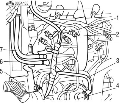
Figure 4.103. Disconnecting the fuel lines: 1 - wiring harness; 2 - crankcase ventilation hose; 3, 4, 6, 7 - fuel lines; 5 - support
- move the tourniquet 1 (figure 4.103) wires;
Attention! Each time the high pressure hoses are removed, they must be replaced with new ones.
- disconnect and move aside hose 2 of the crankcase ventilation system;
- disconnect fuel lines 3, 4, 6, 7 and close them using the device;
- move aside fuel lines 3, 4, 6, 7;
- remove support 5;
- clean the high pressure fuel lines before unscrewing them;
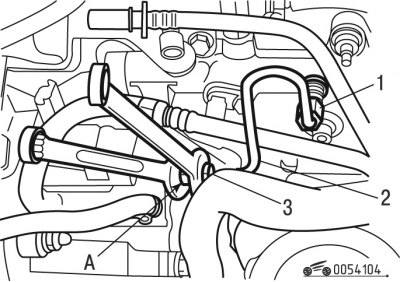
Figure 4.104. Application of counter-coating: 1, 3 - nipples; 2 - fuel line; A - place of application of the counter-coating
- apply counter-coat at location A (figure 4.104);
- unscrew nipple 3;
- unscrew nipple 1;
- remove fuel line 2 of the high pressure circuit of the fuel system;
- remove the high pressure fuel lines going to the injectors;
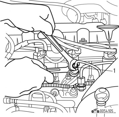
Figure 4.105. Application of counter-coating: B - place of application of the counter-coating composition
- apply counter-compound at location B (figure 4.105);
- loosen the tightening torque of the connecting elements leading to the injectors;
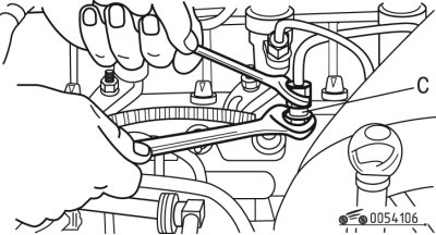
Figure 4.106. Application of counter-coating: C - place of application of the counter-coating
- apply counter-compound at location C (figure 4.106);
- unscrew the connecting elements on the fuel distributor;
- remove high pressure fuel lines;
- close the holes with plugs using the device;
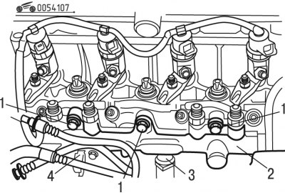
Figure 4.107. Removing the fuel distributor: 1 - bolts; 2 - distributor; 3 - high pressure sensor; 4 - fuel temperature sensor
- disconnect sensor 3 (figure 4.107) high pressure fuel;
- disconnect fuel temperature sensor 4;
- unscrew bolts 1;
- remove the fuel distributor of the direct fuel injection system.
Install the fuel distributor in the following order:
Note: Replace the removed high pressure fuel lines.
- install distributor 2 (see figure 4.107) direct injection fuel system;
- install bolts 1;
- connect high fuel pressure sensor 3;
- connect fuel temperature sensor 4;
- install fuel line 2 (see figure 4.104) high pressure circuit of the fuel system, tightening fittings 1 and 3 by hand;
- connect the fuel lines to the injectors, tightening the connections by hand;
- tighten fittings 1 and 3 to 20 Nm, applying a locking compound at location A;
- tighten bolts 1 (see figure 4.107) torque of 23 Nm;
- apply counter-compound at location B (see figure 4.105);
- tighten the connections of the injectors to the fuel lines with a torque of 20 N·m using tools;
- apply counter-compound at location C (see figure 4.106);
[Original published on the portal: www.PEUGEOTBOOK.ru]
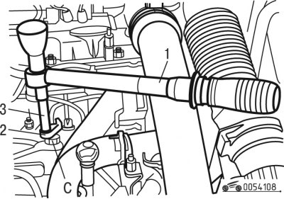
Figure 4.108. Tightening the fuel line connection using tools: 1, 2, 3 - devices; C - place of application of the counter-coating
- tighten the connecting elements on the fuel distributor to a torque of 20 Nm using tools 1, 2, 3 (figure 4.108);
- install support 5 (see figure 4.103);
- connect fuel lines 3, 4, 6, 7;
- install branch pipe 2;
- install wiring harness 1;
- install the engine casing;
- connect the wire to the negative terminal of the battery;
- check the tightness of the fuel system connections by starting the engine and setting the crankshaft speed to 1000 min⁻¹. Press the accelerator pedal several times, bringing the crankshaft speed to 3500 min⁻¹.