



- lUCAS high pressure pump adjustment device - (0188-H);
- electronic engine immobilizer.
Note: This is a case where locking and unlocking the module is possible. The module must be unlocked before removing the fuel pump.
Perform the module unlocking procedure in the following order:
- open the driver's window;
- close all car doors;
- turn on the ignition without opening the doors;
- wait about 10 seconds;
- turn off the ignition without opening the doors;
Attention! If the doors were opened after the ignition was turned off, wait 15 seconds and start the procedure again.
- disconnect the engine control module or fuel pump module.
Attention! The time provided for removing this element is 10 minutes, after this time, start the procedure again. This procedure allows you to make sure that the module is really not locked and check the fuel pump on the stand (without changing the module).
Check the high-pressure fuel pump on the bench in the following order:
- if the module is not locked, the fuel pump will operate if power is supplied to the solenoid valve connector installed on the pump: wire 1 (+12 V) and wire 4 (ground).
Remove the fuel injection pump in the following order:
- disconnect the negative battery cable;
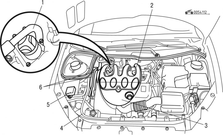
Figure 4.112. Removing engine parts: 1, 4 - tubes; 2 - air distributor; 3 - casing; 5 - electronic control unit; 6 - fuel lines
- remove cover 3 (figure 4.112) engine;
- remove air distributor 2;
- remove pipe 1 of the EGR valve;
- disconnect fuel lines 6;
- disconnect tube 4;
- disconnect the contact connector of the electronic control unit 5;
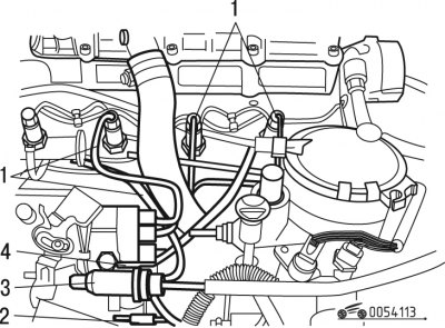
Figure 4.113. Disconnecting the clutch cable: 1 - fuel lines; 2, 3 - cables; 4 - tube
- disconnect and move aside tube 4 (figure 4.113);
- release the flexible cable 3 of the clutch drive from the clamps;
- release the cable 2 for controlling the engine idle speed from the clamps;
- disconnect fuel lines 1 of the injection system;
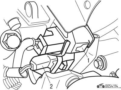
Figure 4.114. Disconnecting the contact connectors: 1, 2 - pin connectors
- disconnect pin connectors 1 and 2 (figure 4.114);
- remove the accessory drive belt;
- remove the timing belt, see. "Timing mechanism (GRM)";
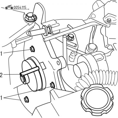
Figure 4.115. Removing the fuel injection pump: 1 - bolts; 2 - device
- remove the fuel injection pump drive pulley using tool 2 (figure 4.115);
- unscrew the three bolts 1 of the pump mount;
- remove the rear fuel pump mount;
- remove the high pressure fuel pump;
- remove device 2.
Install the fuel injection pump in the following order:
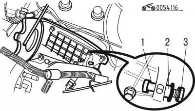
Figure 4.116. Installing the high-pressure fuel pump: 1 - bolts; 2 - spacer; 3 - nut
- make sure bolt 1 is present (figure 4.116) and 2 spacers on the high pressure fuel pump support;
- reinstall the fuel pump;
- reinstall the three fuel pump front mounting bolts and tighten to 20 N·m;
- tighten nut 3 to 22.5 Nm;
- install the fuel lines, tightening the fasteners to a torque of 2.5 N·m;
- install fixture 2 (see figure 4.115);
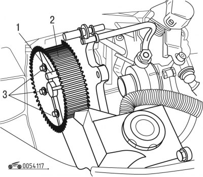
Figure 4.117. Installing the fuel injection pump drive pulley: 1 - device; 2 - pulley; 3 - bolts
- install pulley 2 (figure 4.117) fuel injection pump drives;
- tighten three bolts 3 fastening with a torque of 23 Nm;
- install the timing belt of the gas distribution mechanism;
- install the accessory drive belt.
Proceed with installation in the reverse order of removal.
Program all electronic devices in the vehicle.