



- mark 1 (in the form of a blue paint spot - class 1 nozzle);
- mark 2 (in the form of a green paint spot - class 2 nozzle).
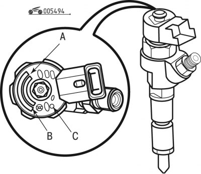
Figure 4.94. Injector markings: A - supplier; B - Peugeot company identification number; C - class identification
The marking shown in Figure 4.94 indicates:
- supplier (A);
- peugeot Company Identification Number (B);
- class identification (C).
Attention! When replacing injectors, 4 injectors of the same class must be installed on the engine.
When removing and installing fuel injectors at Peugeot service centers, the following special tool is used:
- tube Wrench - 1603-F (4220-TD);
- tube Wrench - 1603-G (4220-TC);
- set of plugs - 0188-T;
- compression coupling 1603-A/E/B/D [4220-T(BGJ)].
Remove the fuel injectors in the following order:
- remove the engine protective cover;
- disconnect the negative battery cable;
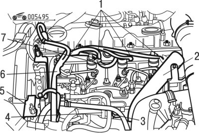
Figure 4.95. Removing fuel system components: 1 - pin connectors; 2 - tube; 3, 4 - sensors; 5 - support; 6 - wiring harness; 7 - branch pipe
- disconnect sensors 3 and 4 (figure 4.95);
- disconnect the contact connectors of 1 injectors;
- move aside the tube 2 of the oil aerosol collector;
- move aside the wiring harness 6;
Attention! Each time the high pressure hoses are removed, they must be replaced with new ones.
- remove fuel return pipe 7;
- close the holes with a device;
- remove caliper 5;
Caution: Clean the fuel line fittings before unscrewing them.
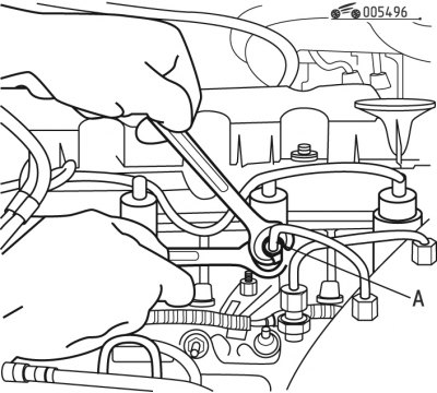
Figure 4.96. Application of counter-coating in zone A
- apply counter-coat in zone A (figure 4.96);
- unscrew the connecting elements;
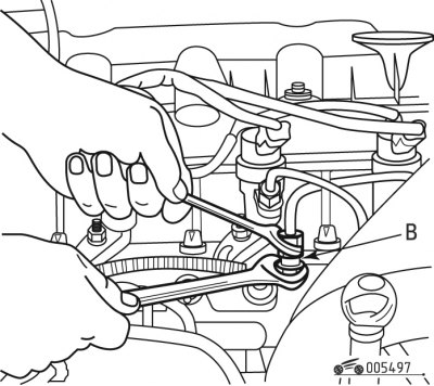
Figure 4.97. Application of counter-welding compound in zone B
- apply counter-coat in zone B (figure 4.97);
- unscrew the connecting elements on the fuel distributor;
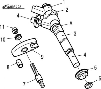
Figure 4.98. Fuel injector parts: 1, 4 - plugs; 2, 11 - nuts; 3 - nozzle; 5 - sealing ring; 6 - leather pad; 7 - hairpin; 8 - thrust washer; 9 - bracket; 10 - washer
- remove four high pressure pipes;
Caution! Do not touch nut 2 (figure 4.98).
- unscrew the nuts of the 11 injectors;
- remove washers 10;
- remove the injector mounting brackets 9;
- remove injectors 3;
- remove the sealing rings 5;
- remove leather pads 6;
- remove thrust washers 8;
Note: If it is impossible to remove the injector, remove stud 7 using a lock nut, then use a flat wrench to turn the injector in the area of the flat A.
- close the nozzle holes 1 and 4 with plugs.
Install the fuel injectors in the following order:
Attention! WarningsReplace the removed high-pressure fuel lines.When unscrewing nuts 11, studs 7 may unscrew together with the nuts, in this case, when reinstalling the studs, be sure to orient the studs in the correct direction (do not install upside down).
- screw the studs into the cylinder head using the nut and lock nut, tightening to a torque of 7.5 N·m;
Attention! When reinstalling, observe the correct bending direction of bracket 9. Observe the correct installation direction of washers 10.
- remove the plugs from the injector holes;
- install thrust washers 8;
- install new leather pads 6;
- install new o-rings 5;
- install the injectors 3, securing them with brackets 9;
- install washers 10;
- install new nuts 11;
- secure the high pressure fuel lines to the injectors and fuel distributor;
- tighten nuts 11 to 30 Nm;
- apply counter-coat in zone A (see figure 4.96);
- tighten the high pressure fuel lines using tools to a torque of 20 Nm;
- apply counter-coat in zone B (see figure 4.97);
- install caliper 5 (see figure 4.95);
- install branch pipe 7;
- install the wiring harness 6 in its place;
- install the branch pipe 2 in place;
- connect the contact connectors 1 to the injectors;
- connect the wire to the negative terminal of the battery;
- check the tightness of the connections by setting the engine speed to 1000 min⁻¹ and pressing the accelerator pedal, setting the crankshaft speed to 3500 min⁻¹.
Original publication on the website (www.peugeotbook.ru)
Complete installation in the reverse order of removal.