English Русский
Български
Беларускі
Український
Српски
Hrvatski
Română
Polski
Slovenský
Magyar
Bookmark Articles Sitemap Contacts
Company Hyundai Company Opel Company Skoda Company Kia Company Mitsubishi Company LADA Company Audi
PeugeotBook.ru


Series 100   Series 200   Series 300   400-500   Series 600   Crossovers   Others
 
Peugeot 305 (1977-1989) Peugeot 306 (1993-2002) Peugeot 307 (2001-2008)

Torpedo — removal and installation (Peugeot 305)

  • Main
  • 30X
  • Peugeot 305 (1977-1989)
  • Body and interior
  • Interior (internal elements)
  • Torpedo — removal and installation
0
1. Removing the dashboard is a fairly simple job, but involves many small operations. It's essential to work methodically and carefully record details such as wire routing, bolt locations and lengths, grounding locations, fasteners, and so on. Under the dashboard is a sound-insulating material, all components of which must be carefully assembled and subsequently installed.

2. It is impossible to give a detailed procedure for removing the dashboard, since it varies from model to model and depending on the year of manufacture of the car. We provide general instructions that can be used for all Peugeot 305 models.

3. Disconnect the ground cable from the battery, remove the fuse box fasteners and the air filter. Disconnect the choke cable and its sheath from the carburetor.

4. Disconnect the multi-pin connectors under the fuse box. Disconnect the headlight and engine wiring harness connectors (see B/ Figure 11.1).
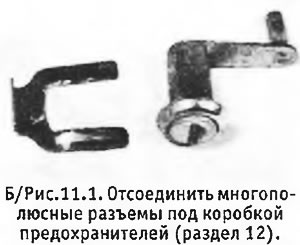
4. Disconnect the multi-pin connectors under the fuse box. Disconnect the headlight and engine…


5. Working inside the cabin, remove the shelf under the dashboard. Remove the steering column cover and unscrew the lower bolts on the side surfaces of the footwells. Remove the shelf from the passenger side.
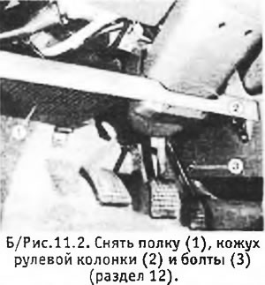


5. Working inside the cabin, remove the shelf under the dashboard. Remove the steering column cover…


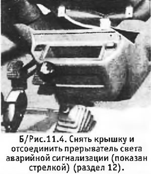
6. Loosen the screws securing the heater cover and remove the cover. Disconnect the hazard warning light switch connector (see B/Figure 11.3 and 11.4).
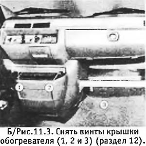
6. Loosen the screws securing the heater cover and remove the cover. Disconnect the hazard warning…

7. Remove 6 screws and take off the "glove compartment" (see B/Figure 11.5).
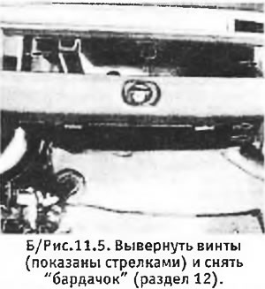
7. Remove 6 screws and take off the «glove compartment» (see B/Figure 11.5).


8. Disconnect the control rods from the heater (see section 16). Disconnect the multi-pin connectors on the wiring harnesses going to the dashboard.
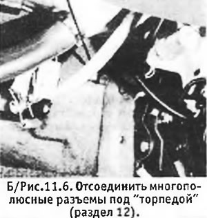


8. Disconnect the control rods from the heater (see section 16). Disconnect the multi-pin…


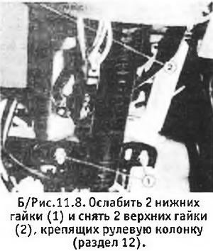
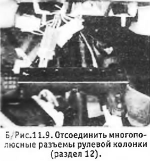
9. Remove the turn signal flasher located on the bracket next to the lower steering column bracket. Loosen the 2 nuts on the lower steering column bracket and remove the 2 nuts from the upper bracket. Disconnect the steering column wiring multi-pin connectors (see B/Figure 11.7, 11.8 and 11.9).
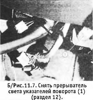
9. Remove the turn signal flasher located on the bracket next to the lower steering column bracket.…

9. Remove the turn signal flasher located on the bracket next to the lower steering column bracket.…


10. Disconnect the brake light switch located on the brake pedal bracket and disconnect the 3 ground wires. Remove the wiring harness from its mountings and release the wires going to the steering column and to the engine compartment bulkhead.
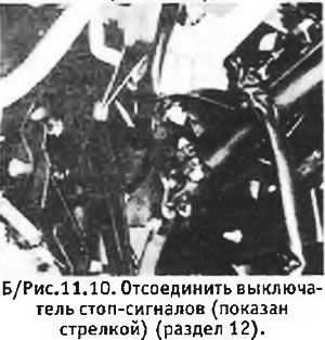


10. Disconnect the brake light switch located on the brake pedal bracket and disconnect the 3…


11. Disconnect the speedometer drive cable by pulling it sharply out of the instrument panel.

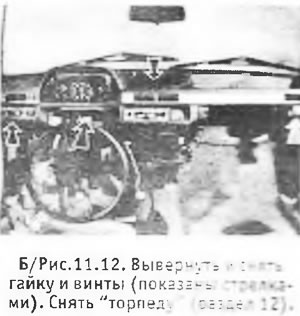
12. Pry off the plastic grille in the center upper part of the dashboard. Loosen the central mounting screw, working through the hole left after removing the grille. Remove the "torpedo" mounting nut located behind the steering column, unscrew the 2 side mounting screws and remove the "torpedo" (see B/Figure 11.11 and 11.12).
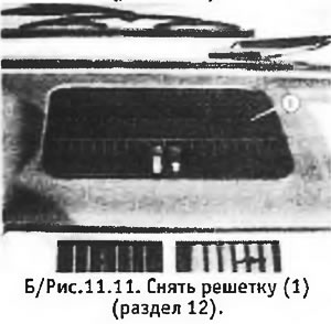
12. Pry off the plastic grille in the center upper part of the dashboard. Loosen the central…

Source available here (PeugeotBook.ru)

13. Installation of the torpedo is carried out in reverse order. If you marked the positions of all the parts as recommended at the beginning of the section, there should be no problems. Tighten the steering column nuts to 1 kg m. Heater installation procedure see section 16. Upon completion, check the operation of all devices and circuits affected during the removal of the dashboard.
This article is available at russian, bulgarian, belarusian, ukrainian, serbian, croatian, romanian, polish, slovak, hungarian
Article reviewed by editor: Ostrovsky Fedor
Share information:
Previous
Peugeot 305: Interior (internal elements)
Next

Glove Compartment Latch Repair (Pre-1983 Models)
Modification of front seat belt anchorages (all models)
Seat belts — description and maintenance
Removal and installation seats
Heater core — removal and installation
Windshield — removal and installation
Interior heater — removal and installation
Removal and installation the heater (models produced since 1983)
Plastic parts
Link to this article in different formats
Comments and feedback from visitors
No comments yet


Add two numbers 18 + 15


Peugeot 307 (2001-2008) 
  • User manual
  • Keys, doors and alarm
  • Controls and instruments
  • Driving and operation
  • Maintenance
  • Power unit
  • Petrol engines TU3 and TU5
  • Petrol engines EW10
  • Diesel engines DV10
  • Diesel engines DW10
  • Transmission
  • Clutch and drive shafts
  • Mechanical gearbox
  • Automatic gearbox
  • Chassis, running gear
  • Front suspension
  • Rear suspension
  • Steering
  • Brake system
  • Body and interior
  • Exterior (external elements)
  • Interior (internal elements)
  • Doors, locks and windows
  • Heating and air conditioning
  • Electrical equipment
  • Equipment and devices
  • Power devices
  • Airbags
  • Electrical circuits
Peugeot 306 (1993-2002) 
  • General information
  • Introduction to manual
  • Specifications
  • Gasoline engine
  • Engine repair
  • Lubrication system
  • Cooling system
  • Fuel injection
  • Ignition system
  • Diesel engine
  • Engine repair
  • Lubrication system
  • Cooling system
  • Fuel injection
  • Transmission
  • Clutch
  • Gearbox
  • Drive shafts
  • Chassis, running gear
  • Steering system
  • Front suspension
  • Rear suspension
  • Brake system
  • Electrical equipment
  • Power devices
  • Electrical circuits
Peugeot 305 (1977-1989) 
  • General information
  • Maintenance
  • Power unit
  • Gasoline engines
  • Diesel engines
  • Cooling system (gasoline)
  • Cooling system (diesel)
  • Fuel system (gasoline)
  • Fuel system (diesel)
  • Ignition system
  • Transmission
  • Clutch
  • Mechanical gearbox BB8
  • Mechanical gearbox BE1
  • Automatic gearbox ZF4
  • Shafts, hubs and wheels
  • Chassis, running gear
  • Brake system
  • Car suspension
  • Steering
  • Body and interior
  • Exterior (external elements)
  • Interior (internal elements)
  • Electrical equipment
  • Equipment and devices
  • Headlights and lighting
  • Power devices
  • Electrical circuits
  • Wiring diagrams (diesel)
PeugeotBook.ru © 2018–2026 | Mobile version | Sitemap: EN BG BY UA RS HR RO PL SK HU | Write message | Site search | Add to bookmarks | Peugeot owners
106 (1991-2003) | 206 (1998-2012) | 207 (2006-2014) | 305 (1977-1989) | 306 (1993-2002) | 307 (2001-2008) | 405 (1987-1997) | 406 (1995-2004) | 605 (1989-2000) | Partner-I (1996-2008) | Eurovans-807 (2002-2014) | Eurovans-806 (1994-2002) | J5 (1981-1993) |
Cookies are used to ensure the correct display of pages on the site.