



Check and, if necessary, adjust the V-belt tension.
If you have a voltmeter, ammeter and a resistance box, you can carry out the following tests by assembling the test circuit in accordance with Figure 303.
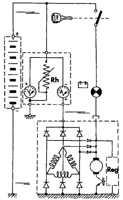
Figure 303. Circuit for checking the voltage and current of the alternator.
You can find the original on the page (PEUGEOTBOOK.ru)
- Disconnect the ground wire from the battery.
- Disconnect the excitation wire from the EXC terminal of the alternator and the charging circuit wire from the positive terminal.
- Connect an ammeter in series and a resistance box in parallel to the charging circuit. The positive terminal of the ammeter should be connected to the alternator terminal and the negative terminal should be connected to the disconnected charging circuit wire. The resistance box must be connected between the negative terminal of the ammeter and ground.
- Connect a voltmeter in parallel to the charging circuit. The positive terminal of the voltmeter should be connected to the alternator terminal and the negative terminal connected to ground.
- Connect the ground wire to the battery.
- Connect the speed meter in accordance with the manufacturer's operating instructions.
- Start the engine and let it run at idle speed. Check that the engine speed is at least 700 rpm and adjust the resistance on the battery pack until the voltmeter reading reaches 14 volts. The ammeter reading should be at least 16 amps.
- Increase the engine speed to 900 rpm and check whether the ammeter reading increases to 32 amps. A further increase in engine speed to 1800 rpm should cause the ammeter reading to increase to 47 amps.
- Turn off the engine and disconnect the ground wire from the battery.
- Disconnect all devices and reconnect the generator wires. Connect the ground wire to the battery.
- The regulator voltage is checked on the same circuit. Increase the speed to 1800 rpm and take readings from the voltmeter and ammeter. At a current of 42 amperes, the voltage should be 13.8 - 14.5 volts.