



Table of contents: Disassembly 🠇 Checking the carbon brushes and…🠇 Checking the rotor 🠇 Checking the stator 🠇 Checking diodes 🠇 Assembly 🠇
Without the necessary experience, it is prohibited to repair the alternator and the associated voltage regulator. A failed generator can be exchanged at the exchange fund. Minor repairs, such as replacing carbon brushes, can be done in a workshop.
The alternator has lifetime lubricated bearings and requires no regular maintenance. The outside of the generator must be clean and no water or solvents must enter it.
The generator brushes work with a smooth commutator and therefore have a long service life. To check the condition of the brushes, it is necessary to remove the alternator. Below is a description of the disassembly and inspection of the Valeo alternator as installed on most vehicles.
Disassembly
Figure 304 shows the installation drawing of the generator.
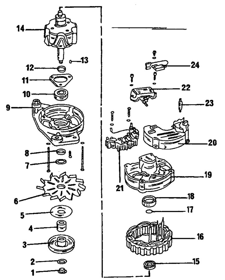
Figure 304. Valeo alternator installation drawing.1. Nut, 40 nm; 2. Washer; 3. Belt pulley, 70 Nm; 4. Expansion sleeve; 5. Washer; b. Fan; 7. Washer; 8. Spacer ring; 9. Drive bearing shield; 10. Drive side bearing; 11. Bearing mounting plate; 12. Spacer ring; 13. Key; 14. Rotor; 15. Bearing on the carbon brush side; 16. Stator; 17. Metal ring; 18. Plastic bushing; 19. Generator housing; 20. Lid; 21. Board with diodes; 22. Voltage regulator; 23. Hairpin; 24. Radio interference suppression capacitor
- Remove the nut from the rotor shaft and remove the belt pulley, fan and spacer washer from the shaft. When removing the shaft, it is necessary to hold it by placing an old V-belt on the belt pulley and clamping the pulley in a vice, as shown in Figure 305. You can also insert a rod wrench into the hexagon of the shaft when unscrewing the nut. To remove the belt pulley, you will need a puller with two or three jaws.
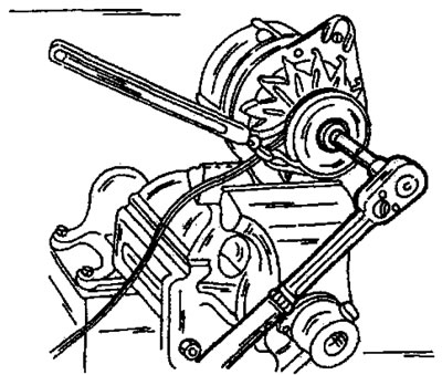
Figure 305. Loosening the nut on the inside of the belt pulley. Place the V-belt on the belt pulley as shown in the figure.
- Remove the key from the shaft.
- Unscrew and remove the voltage regulator together with the brush holder.
- Mark the drive bearing shield and the generator housing on opposite sides and unscrew both studs from the housing. Separate the rear bearing cover from the front. Lightly tap the front cover with a plastic hammer.
- Place the bearing shield and rotor under a press and remove the rotor using a three-jaw puller, as shown in Figure 306. When pressing out the rotor, the bearing mounting plate screws are stripped. Therefore, it is imperative to ensure that the puller jaws are installed under the bearing mounting plate, and not just under the bearing shield. If you need to remove the bearing from the shield, unscrew the screws from the inside and press out the bearing.
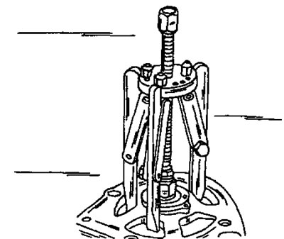
Figure 306. Removing the rotor using a three-jaw puller.
- Press out the bearing from the rotor collector side. If using a puller, position it under the inner bearing race.
- Unsolder the board with diodes from the stator. At the same time, hold the wires at the soldering points with tweezers, which serve as a heat sink. Do not allow the diodes to overheat.
- Rectifier diodes can only be removed if you have the appropriate tools and the necessary knowledge.
Checking the carbon brushes and brush holder
- Check the contact of the brushes with the commutator rings. Check the mobility of the brushes in the guides; if necessary, clean the guides with Tri.
- If the protruding length of the brushes is less than 5.0 mm (Figure 307), new brushes should be soldered in. When the brushes approach this size, they should also be replaced to save on one generator disassembly. Use a ruler for measurements.
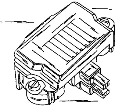
Figure 307. The ends of the brushes must protrude at least 5 mm.
Checking the rotor
If the commutator rings are dirty or oily, wipe them with a cloth soaked in "TP" cleaner. Polish any scratches with fine sandpaper. To check the insulation, connect one end of the ohmmeter to the rotor core and the other to the collector rings. If the ohmmeter reading is different from "infinity", the rotor should be replaced. The measurement is carried out as shown in Figure 308.
(Text taken from the website: Peugeotbook.ru)
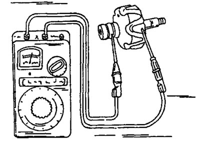
Figure 308. Rotor winding insulation testing diagram. Connect one end of the ohmmeter to the rotor core and the other to the collector rings.
The rotor winding resistance is checked by connecting both ohmmeter leads to the collector rings (Figure 309). The resistance should be between 3.4 and 3.7 mm. If the resistance is "infinity," there is an open circuit in the winding. If the reading is zero, there is a short circuit in the winding. In both cases, the rotor must be replaced.

Figure 309. Checking the rotor winding resistance. The ohmmeter wires are connected to the collector rings.
Checking the stator
In the case of a short circuit, which is usually the result of severe overheating, the location of the damage is already revealed during an external inspection. Otherwise, connect one ohmmeter lead to the stator lamellar ring and connect the other end in series to each of the three stator winding wires, as shown in Figure 310. The ohmmeter reading should be "infinity" in all measurements. To check the stator winding resistance, connect the ohmmeter leads in series to two of the three winding wires, as shown in Figure 311. If there is no reading, the winding is open. The resistance should be 0.10-0.11 ohms.
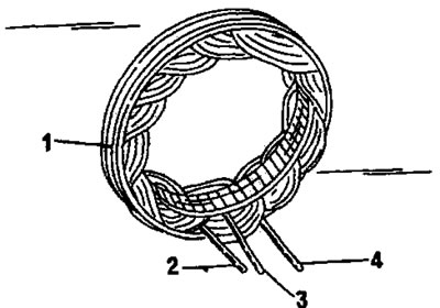
Figure 310. Checking stator windings for short circuits. Connect the ohmmeter to the lamellar ring (1) and in series to the wires of windings 2, 3 and 4. The resistance should be equal to infinity.
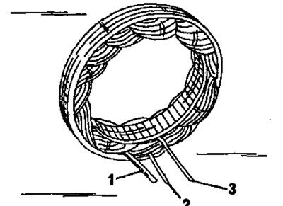
Figure 311. Connect an ohmmeter in series to the ends of windings 1 and 2, 1 if 3, and also 2 and 3. The resistance should be equal to the values given in the text.
Checking diodes
Accurate testing of the electrical characteristics of diodes requires a special test device and should only be performed in a workshop.
Assembly
Figure 304 shows the installation drawing of the Valeo generator; when assembling, please use this drawing.