
English Русский
Български
Беларускі
Український
Српски
Hrvatski
Română
Polski
Slovenský
Magyar
Bookmark Articles Sitemap Contacts
Company Hyundai Company Opel Company Skoda Company Kia Company Mitsubishi Company LADA Company Audi
PeugeotBook.ru


Series 100   Series 200   Series 300   400-500   Series 600   Crossovers   Others
 
Peugeot 305 (1977-1989) Peugeot 306 (1993-2002) Peugeot 307 (2001-2008)

Turbocharger — removal and installation (Peugeot 306)

  • Main
  • 30X
  • Peugeot 306 (1993-2002)
  • Diesel engine
  • Fuel injection
  • Turbocharger — removal and installation
0
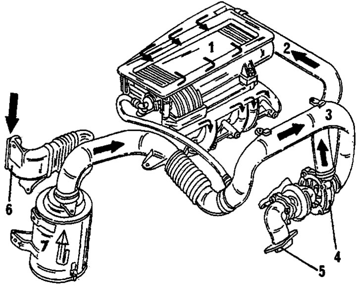
Figure 429 shows the layout of the turbocharger and air intake system of a turbodiesel engine. The turbocharger is connected to the air filter and charge air cooler and is bolted to the intake manifold pipe at the other end.

Figure 429. Turbodiesel air intake channel.1. Charge air cooler;2. Hose connecting the turbocharger…

Figure 429. Turbodiesel air intake channel.1. Charge air cooler;2. Hose connecting the turbocharger and charge air cooler;3. Hose connecting the turbocharger and charge air cooler;4. Turbocharger;5. Exhaust manifold fitting;6. Air intake inlet; 7. Air filter with filter element
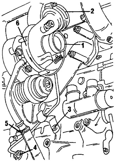

Figure 430. Installed turbocharger.1. Hose nipple; 2. Air intake hose; 3. Oil pipe mounting…

Figure 430. Installed turbocharger.1. Hose nipple; 2. Air intake hose; 3. Oil pipe mounting bracket; 4. Lubricant supply tube; 5. Return lubrication tube; 6. Turbocharger


Figure 430 shows the installed turbocharger. The connecting hose is already connected. Before removal, the front of the vehicle should be supported on stands to allow access to some components. Disconnect the ground wire from the battery and then perform the following work:


  • Remove the charge air cooler (1) in Fig. 429.
  • Disconnect the air hoses (2) and (3) at both ends and remove the hoses.
  • Remove the air intake manifold This part is located directly behind the cylinder head cover. The manifold is secured with six bolts and one slightly hidden bolt (to the left of the turbocharger hose connection nipple).
  • Trace the lubrication supply pipe routing and unscrew the union nut from the turbocharger. Carefully pull out the tube.
  • To the right of the connection point of the tube there is a turbocharger mounting bolt. Turn it away as well.
  • Disconnect the gear shift rods from under the vehicle and disconnect the center shaft.
  • Unscrew the two nuts and other fastening elements connecting the muffler pipe to the turbocharger.
  • Locate the oil drain pipe in Fig. 430 and either disconnect the hose (5) or remove the two Allen head bolts from the turbocharger fitting flange. Pick up the phone.
  • Unscrew the union nut (4) in Figure 430 and remove the oil pipe. To release the tube from the clamp, unscrew the bolt (3).
  • Locate the two remaining turbocharger mounting bolts and, after unscrewing them, pull the turbocharger out from the underside of the car along with the muffler pipe still bolted on. Both bolts are located directly above the oil line fitting.

The turbocharger is installed in reverse order, observing the following points:
  • Check the air filter system, i.e. the filter element must be clean and there should be no leaks in the intake device.
  • Check for foreign objects in the intake and exhaust systems. Foreign objects can cause the turbocharger to fail.
  • Thoroughly clean the pipe connections. When connecting them, install new sealing rings.
  • Turbocharger mounting bolts are heat resistant. Install only these bolts.

Installation is carried out in reverse order:


  • Install the turbocharger in the correct position and tighten the two bolts on the left and right and one bolt near the oil pipe connection. Before tightening the bolts to 55 Nm, tighten them by hand.
  • Connect the lubrication supply line, screw on both union nuts, and tighten them to a torque of 20 Nm. One of the nuts is located on the turbocharger, and the other is at the lower end of the line.
  • Connect two air hoses to the turbocharger and secure them with clamps.
  • Connect the muffler pipe to the turbocharger. Tighten the nuts to a torque of 10 Nm.
  • Connect the gear shift rods.
  • Connect the return oil hose either to the tube or to the top end. Screw on the mounting bracket and tighten.
  • Screw on the air intake manifold. Tighten the bolts to 23 Nm. Then install the charge air cooler and connect the battery.
  • Disconnect the shut-off control wire from the high-pressure fuel pump and crank the engine with the starter until the oil pressure warning lamp goes out. In this case, the turbocharger is filled with oil before it is driven by the engine. After connecting the wire, leave the engine running for approximately 30 minutes at idle speed, without increasing the engine speed, and check for leaks at the connection points.
This article is available at russian, bulgarian, belarusian, ukrainian, serbian, croatian, romanian, polish, slovak, hungarian
Article reviewed by editor: Shirokov Arseny
Share information:
Previous
Peugeot 306: Fuel injection
Next

Lucas high pressure fuel pump
Bosch high-pressure fuel pump (turbo diesel engine)
Bosch high-pressure fuel pump (except turbodiesel engines)
Adjusting the high-pressure fuel pump
Glow plugs
Air filter
Turbocharger malfunctions
Brief information about turbochargers
See similar information for other Peugeot models

➨ Turbocharger Cooling Pump Replacement (EP6DT Engines) Peugeot 207 (2006-2014)
➨ Removal and installation a turbocharger Peugeot 405 (1987-1997)
➨ Turbocharger — operating principle Peugeot 605 (1989-2000)
➨ Cooling system. 2.0-liter engine with a turbocharger and one Peugeot 806 (1994-2002)
Link to this article in different formats
Comments and feedback from visitors
No comments yet


Add two numbers 24 + 30


Peugeot 307 (2001-2008) 
  • User manual
  • Keys, doors and alarm
  • Controls and instruments
  • Driving and operation
  • Maintenance
  • Power unit
  • Petrol engines TU3 and TU5
  • Petrol engines EW10
  • Diesel engines DV10
  • Diesel engines DW10
  • Transmission
  • Clutch and drive shafts
  • Mechanical gearbox
  • Automatic gearbox
  • Chassis, running gear
  • Front suspension
  • Rear suspension
  • Steering
  • Brake system
  • Body and interior
  • Exterior (external elements)
  • Interior (internal elements)
  • Doors, locks and windows
  • Heating and air conditioning
  • Electrical equipment
  • Equipment and devices
  • Power devices
  • Airbags
  • Electrical circuits
Peugeot 306 (1993-2002) 
  • General information
  • Introduction to manual
  • Specifications
  • Gasoline engine
  • Engine repair
  • Lubrication system
  • Cooling system
  • Fuel injection
  • Ignition system
  • Diesel engine
  • Engine repair
  • Lubrication system
  • Cooling system
  • Fuel injection
  • Transmission
  • Clutch
  • Gearbox
  • Drive shafts
  • Chassis, running gear
  • Steering system
  • Front suspension
  • Rear suspension
  • Brake system
  • Electrical equipment
  • Power devices
  • Electrical circuits
Peugeot 305 (1977-1989) 
  • General information
  • Maintenance
  • Power unit
  • Gasoline engines
  • Diesel engines
  • Cooling system (gasoline)
  • Cooling system (diesel)
  • Fuel system (gasoline)
  • Fuel system (diesel)
  • Ignition system
  • Transmission
  • Clutch
  • Mechanical gearbox BB8
  • Mechanical gearbox BE1
  • Automatic gearbox ZF4
  • Shafts, hubs and wheels
  • Chassis, running gear
  • Brake system
  • Car suspension
  • Steering
  • Body and interior
  • Exterior (external elements)
  • Interior (internal elements)
  • Electrical equipment
  • Equipment and devices
  • Headlights and lighting
  • Power devices
  • Electrical circuits
  • Wiring diagrams (diesel)
PeugeotBook.ru © 2018–2026 | Mobile version | Sitemap: EN BG BY UA RS HR RO PL SK HU | Write message | Site search | Add to bookmarks | Peugeot owners
106 (1991-2003) | 206 (1998-2012) | 207 (2006-2014) | 305 (1977-1989) | 306 (1993-2002) | 307 (2001-2008) | 405 (1987-1997) | 406 (1995-2004) | 605 (1989-2000) | Partner-I (1996-2008) | Eurovans-807 (2002-2014) | Eurovans-806 (1994-2002) | J5 (1981-1993) |
Cookies are used to ensure the correct display of pages on the site.