



Table of contents: Adjusting the idle speed increase…🠇 Adjusting the idle speed increase…🠇 Accelerator cable 🠇 Adjusting the engine stop speed 🠇 Idle speed adjustment 🠇 Adjusting the idle speed transition…🠇
Adjustments are made using Figure 427.
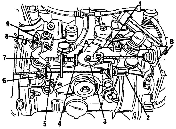
Figure 427. Lucas high-pressure fuel pump adjustment. References to numerical and letter designations are given in the text.
Adjusting the idle speed increase device - cold engine
- Check on a cold engine that the lever (7) is on the stop by pressing it in the direction of the arrow. If necessary, adjust the cable (5) using the adjusting screw (6). In doing so, tighten the cable sheath (2) accordingly.
Adjusting the idle speed increase device - the engine is warm
Warm up the engine to operating temperature and check that the idle speed increase control cable (5) on the front side of the pump is loose (This is a cable controlled by the idle speed increase device thermostat.) There should be a difference in cable tension of at least 6 mm between a cold and hot engine. If this is not the case, the thermal capsule in the cooling system fitting may be defective.
Accelerator cable
Turn off the engine. Have an assistant fully depress the accelerator pedal and check that the lever (3) rests against the stop (1). If it doesn't, adjust the accelerator cable at location (B) by moving the clamp at the end of the cable. The idle lever (3) must be positioned on the stop (4).
Adjusting the engine stop speed
When adjusting, the engine must be warm. The idle speed increase device must be free, that is, the free play "A" in Figure 426 must be within the range of 0.5 to 1.0 mm.
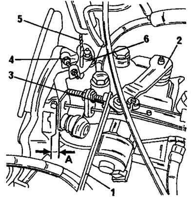
Figure 426. Lucas high-pressure fuel pump adjustment. Shown primarily are the engine shutoff speed adjustment elements. 1. Probe; 2. Accelerator lever; 3. Stop screw; 4. Thrust lever; 5. Blocking drill; 6. Locked lever
- Start the engine and insert a 3.0 mm thick washer into place "A" between the lever (3) and the stop screw (4). Press the lever (4) in Figure 426 and insert a 3 mm diameter drill into the lever (6). Loosen the lock nut of the screw (4) and turn the screw, setting the speed to 900±50 rpm. Tighten the lock nut. Remove the drill and feeler gauge.
Idle speed adjustment
- Adjust the idle speed with screw (8) after loosening the lock nut. The engine should run at 750–800 rpm. When adjusting, aim for 800 rpm. With an automatic transmission or air conditioning, the idle speed should be 50 rpm higher. Tighten the lock nut.
Check that after adjustment the lever is on the stop.
Adjusting the idle speed transition process
After this, it is necessary to check the transition to idle speed. To check, bring the engine speed up to 3000 rpm and then release the throttle lever (2) in Fig. 428. If the transition occurs too quickly (sometimes the engine even stalls), loosen the screw a quarter turn; if the process is slow (the engine does not return to idle speed within a reasonable time), screw in the stop screw (4) a quarter of a turn. Naturally, with both adjustments it is necessary to loosen the lock nuts. After completing the adjustment, check the idle speed again.
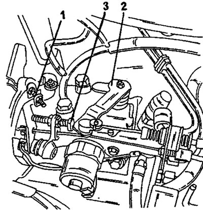
Figure 428. Adjusting the idle speed transition process. 1. Idle speed adjustment screw; 2. Accelerator lever; 3. Stop screw
Note: Ignition pulse speed meters used for adjusting petrol engines are not suitable for diesel engines. That is, all the above adjustments must be performed using a speed meter designed for diesel engines.