



- Drive onto an overpass or a pit and lift the car with a jack until the wheels sag.
- In the car's interior, remove the handbrake lever cover, unscrew the locknuts and adjusting nuts from the end of the handbrake cable from which the longitudinal lever should be removed, and pull the cable out of the swivel roller. In Figure 235 the handbrake cable fastenings are indicated by arrows.
- Release the cable from the two mounting clamps under the fuel tank and pull it out of the guide on the bottom.
- Remove the torsion bars following the instructions in section 12.4.
- Unscrew the brake pipe from the wheel brake cylinder on the corresponding side. To prevent dirt from getting in, close the tube with a stopper. Pull out the ersatz shock absorber (the above mentioned rod used to remove the torsion bars) and pull the trailing arm out of the wheel suspension.
- Pull out the oil seal with a screwdriver (Figure 239). If necessary, also remove the bushing from the hole.
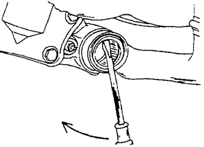
Figure 239. Removing the oil seal from the trailing arm using a screwdriver.
Before installation, thoroughly clean all removed parts. Check both surfaces of the steel liners; they must be clean and free from scratches and other damage. The support surfaces on the support axis of the longitudinal arm, both outside and inside, must not be damaged. On a vehicle without an anti-roll bar, check that the plugs in the holes where the anti-roll bar is usually mounted do not leak. Otherwise, new plugs need to be inserted.
Installation is carried out as follows:
- Lubricate the sealing lips of the new trailing arm oil seal (shown in Figure 239) and insert the seal into the support insert. Place the outer sponge on the trailing arm side.
- Lubricate the needle bearing and the bearing surface of the trailing arm with general-purpose grease.
- Insert the support axle into the wishbone until the oil seal touches the support sleeve.
- Place the special template 0526 0 as shown in Figure 240 and also install the ersatz shock absorber. While moving the template upward, tighten the nut to bring it as close to the sleeve as possible.
- Insert a 0.5 mm thick feeler gauge between the template and the body of the transverse arm (at location "A" in Figure 240) and strike the longitudinal arm with a soft metal hammer until the template is pressed against the feeler gauge. The trailing arm is installed correctly if the feeler gauge enters and is pulled out with tension.
- Place a stand under the brake drum or lift the drum with a jack so that the longitudinal lever is in its correct position, and remove the shock absorber surrogate and the template.
- Connect the brake pipe and screw on the union nut.
- Install the torsion bar.
- Install the anti-roll bar.
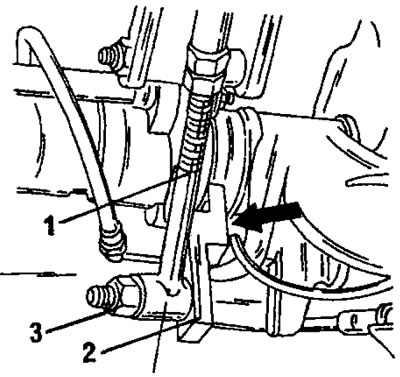
Figure 240. Installing the ersatz shock absorber (1) and the named template (2). Tighten the parts with the nut (3).
Source available on the website PeugeotBook.ru