



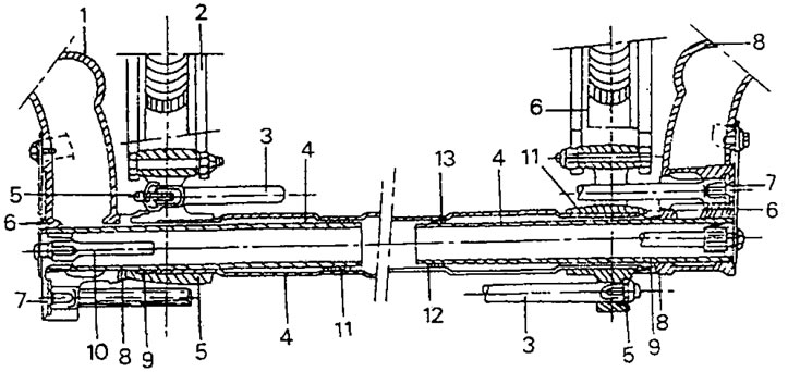
Figure 252. Section of the rear axle. 1. Trailing arm; 2. Rear axle beam; 3. Torsion; 4. Trailing arm support axis; 5. Torsion bar mounting bolt; 6. Stabilizer link arm; 7. Torsion bolt; 8. Stirrup seal with sealing lips; 9. Needle bearing; 10. Anti-roll bar; 11. Rear axle pipe housing; 12. Bridge pipe; 13. Inner bearing
- Raise the rear of the car. The wheels should sag.
- Remove the wheels.
- On the right side, remove the bolt with the washer securing the lever to the trailing arm and pull out the plug from the outer end of the stabilizer rod. The arrangement of the parts is shown in Figure 253.
- Lubricate the threads of the special release bolt 0908R with graphite grease and screw the bolt into the end of the lever until it rests against the stabilizer rod (Figure 254).
- After this, tighten the bolt in Figure 254 until the pull lever moves away.
- Perform the same work on the left side and pull the stabilizer rod together with the lever out of the bridge tube.
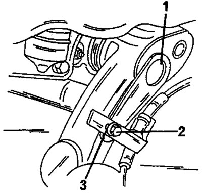
Figure 253. Side view of wheel suspension. The end of the stabilizer link is closed with a plug (1). Bolt (2) secures the lever to the trailing arm. There is a washer (3) under the bolt head.
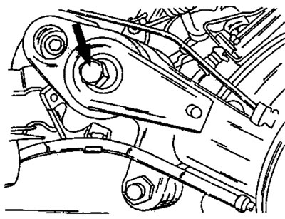
Figure 254. Using a special push-out bolt to install the anti-roll bar.
If it is necessary to remove the lever from the rod, screw the release bolt back in and pull the lever off, just as described for the lever on the right side.
Before installing the stabilizer link, lubricate the spline grooves with EssoNorva 275 grease. Lubricate the threads of the device, as well as the nut and washer with graphite grease.
The installation of the stabilizer link is carried out as follows:
- Secure the stabilizer rod in a vice and select the required lever. The left lever has a marking along the center line of the oblong hole in the lever. Place a new rubber ring on the lever, with the protrusion on the opposite side to the contact surface of the lever. Lubricate the outer side of the rubber ring with KLuber Proba grease. The left side of the stabilizer link is secured with a boss.
- Align the lever so that the mark (b) on the lever matches the mark (a) on the stabilizer link (2). This alignment ensures that both levers are in the same position after installation (Figure 255). In this position, place the lever on the stabilizer rod until it stops.
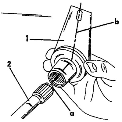
Figure 255. Installing the left arm (1) of the stabilizer link (2). Marks "a" and "b" must be located in line.
- Screw the device into the stabilizer rod, put on the washer and tighten the nut. Holding the bolt by the flat end, tighten the nut until the lever is fully installed on the stabilizer rod, similar to how it is shown in Figure 256 for the installed stabilizer. If the lever is slow to put on, you can put it on using a piece of pipe with a diameter of 30 mm and a length of 70 mm.
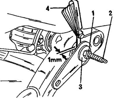
Figure 256. Installing the lever on the stabilizer rod on the right side of the car, with a washer, nut and special bolt. To place the lever on the other stabilizer rod, secure the stabilizer rod in a vice. 1. Nut; 2. Threaded rod; 3. Washer; 4. Probe
- Temporarily screw an M8 x 1.25 bolt into the stabilizer link (no longer than 25 mm) and tighten a little.
- Push the stabilizer into the axle tube from the left side until the lever stops against the trailing arm. Install the bolt (2) with the washer (3) in Figure 252 and tighten the bolt to a torque of 35 Nm. Also secure the handbrake cable support bracket.
- Also prepare the stabilizer link on the right side, that is, install the seal and screw in the clamp bolt again, as shown in Figure 256. Put the lever on so that its other end is located in line with the mounting hole, that is, as shown in Figure 252.
- Place the lever on the stabilizer link as described for the left lever. To maintain the required distance between the lever and the longitudinal lever, place a 1.0 mm thick washer between them, as shown in Figure 256, and tighten the bolt until the lever fits against the washer.
- Install the bolt with the washer and tighten the bolt to a torque of 35 Nm.
- Cover the threads of the plug with sealing compound and screw the plug on.
- Screw the plug on from the opposite side.
- All other work is carried out in reverse order and after this the car is lowered onto its wheels. Tighten the wheel nuts to the specified torque.
View the original on the website (PEUGEOTBOOK)