
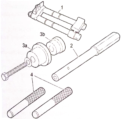
Recommended fixtures:
1 - a device for blocking the belt pulley 1 860 765 000;
2 - calibration pin of the camshaft pulley 0194.B;
For - mounting mandrel of the camshaft oil seal 0194.K1;
Zb - mounting cone 0194.K2;
4 - rod for assembling the camshaft holder 0194.N.
Removing
Remove:
- air ducts at the inlet and outlet of the turbocharger (see corresponding operation);
- air supply system (see corresponding operation);
- diesel injectors (see corresponding operation).
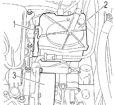
Remove:
- fuel filter (2) (see corresponding operation);
- fuel filter bracket (1);
- Vacuum pump (3) (see corresponding operation).
Remove (see related operations):
- attachment drive belt;
- implement drive belt.
Visually check the condition of the timing belt.
Attention. If the belt has cracks or traces of oil, it must be replaced.
Remove (see related operations):
- attachment drive belt;
- implement drive belt.
Visually check the condition of the timing belt.
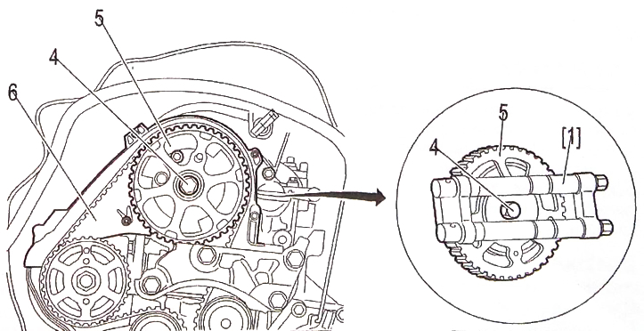
Attention. Block the camshaft pulley (5) with tool 1.
Remove:
- bolt (4);
- camshaft pulley (5);
- timing case (6).
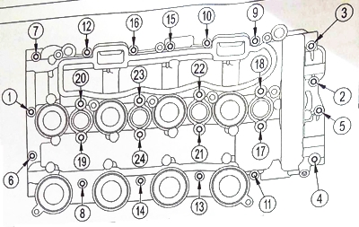
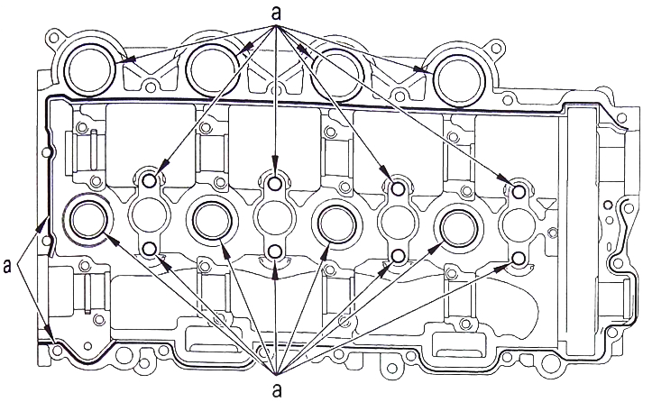
Note. Follow the specified tightening sequence (order 1 to 24).
Remove:
- bolts (order 1 to 16);
- hairpins (order from 17 to 24).
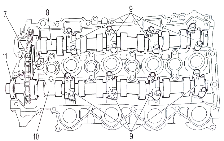
Separate the camshaft bearing cap housing and remove it.
Note. Mark the location of the camshaft bearing caps (9).
Sequentially unscrew the screws of the camshaft bearing caps.
Remove:
- stuffing box (11);
- camshaft bearing caps (9);
- timing chain tensioner (7);
- camshafts (8) And (10).
Mark the position of the rockers (12) and pushers.
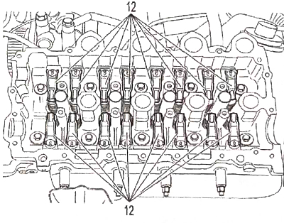
 |  |
Examination
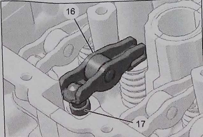
Note. Check the condition of the rocker arms (16) and hydraulic pushers (17) and the condition of the camshaft bearing caps.
Attention. Clean the surfaces to be joined with a metal remover. Do not use abrasive or scratching tools on the surfaces to be joined, they must not show signs of impact or cracks.
Attention. Mark the position of the rockers (16) and hydraulic pushers (17).
Make sure the hydraulic lifters move freely.
Before installing the crankcase of the camshaft bearing caps, check the operation of the rocker arms and hydraulic pusher (bearing rotation, surface condition).
Check the condition of the cam surfaces of the intake and exhaust camshafts.
Check the condition of the chain tensioner (freedom of displacement tension state of surfaces).
Check the condition of the drive chain. Replace defective parts.
Attention. When installing, all previously removed gaskets must be replaced with new ones.
Install fixing springs (16a) on the rocker (16).
Note. Springs (16a) are supplied in a repair kit.
Detent spring position (16a): «b» - side without protrusion; «With» - protrusion side.
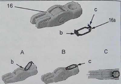
Attention. Before installation, make sure that the fixing springs are not deformed.
Stage «A»: position the spring (16a) side «b» on the inner edge of the rocker roller.
Stage «IN»: snap the spring with the side «With» on the outer edge of the rocker.
Stage «WITH»: Check if the installation is correct.
Lubricate the hydraulic tappet housings with engine oil (17) and rockers (16).
Install hydraulic tappets (17) (respecting the initial place0; location) and rockers (16) complete with fixing springs (16a) (respecting the initial locations).
Attention. Check the rocker arms and tappets for proper operation before installing the camshaft bearing caps.
Installation
Apply a roller to the crankcase flange of the crankshaft bearings «A» sealant «Autojoint Noir».
Attention. Do not block with sealant the channels through which oil is supplied to the hydraulic tensioners of the timing chain (in the zone «A»).
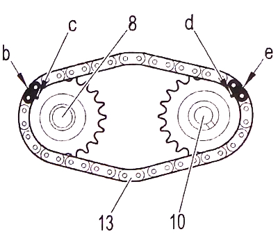
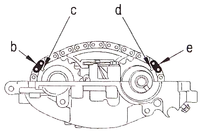
Set the chain (13) on the camshaft sprockets (8) And (10).
Lubricate the camshaft bearing caps (9).
Install:
- chain (13) with chain tensioner (7) and camshafts (8) And (10);
- camshaft bearing caps (9).
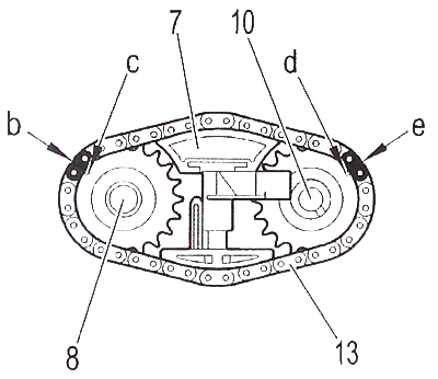
Attention. Make sure the marked links «b» And «e» are opposite the teeth marked «c» And «d», camshaft sprockets. Otherwise, start over with the camshaft installation operation.
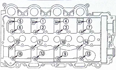
Screw in and then sequentially tighten the mounting screws in the order shown from 1 to 16.
Install seal (11) camshaft using tools 3a and 3b.
Lubricate the tappet housings and bearing surfaces of the camshafts (8) And (10).
Check up, that pushers freely rotated in a head. Install rocker arms (12) (respecting the starting location). Establish a clamp of a yoke on a hinge of a pusher.
Attention. Check the rocker arms and tappets for proper operation before installing the camshaft bearing caps.
Fixing the timing chain
Install the camshaft pulley (5) and bolt (4).
Lock the camshaft pulley with tool 2.
Remove tool 2.
Perform 40 revolutions of the camshafts.
Note. Make sure the marked chain links «b» And «e» are opposite the teeth marked «With» And «b», sprockets of distribution shafts. Otherwise, start the installation operation from the beginning.
Remove the bolt (4) and camshaft pulley (5).
Install tool 4.
Fit the camshaft bearing caps to the cylinder head using tools 4.
Note. Observe tightening sequence (order 1 to 24).
Install:
- hairpins (1 to 8);
- bolts (from 9 to 24).
Remove tool 4.
Install the timing case, camshaft pulley and bolt.
Rotate the camshaft sprocket (5) clockwise using tool 1.
Note. If the pulley is turned too far, return it a quarter of a turn towards the mounting hole (counterclockwise direction).
Camshaft Position Sensor Adjustment
Note. When installing the camshaft position sensor, observe the required air gap between the sensor and the target.
unscrew the bolt (14).
Slide Camshaft Position Sensor (15) into the depth of the cuts.
Screw in the screw (14) for several turns.
Adjust air gap (1.2mm) camshaft position sensor (15).
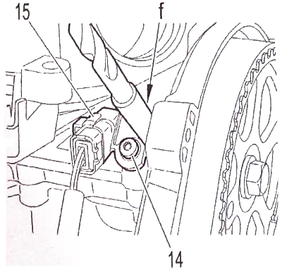
New Camshaft Position Sensor: Engage the camshaft position sensor tab in contact with «target» on the camshaft drive pulley (5).
Camshaft position sensor reuse: position the drill (f) (diameter 9.5 mm) between camshaft position sensor (15) and crankcase gas distribution mechanism (6).
tighten bolt (14).
Install the rest of the parts in reverse order.
Connect the positive and negative battery terminals.
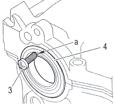
Camshaft oil seal replacement
Block the camshaft pulley with the tool (see description above).
Remove the camshaft pulley and timing case (remove the inserts).
Drill a hole with a diameter of 3.5 mm in the area «A» stuffing box (4).
Screw the tool bolt 3 into the hole in «A».
Remove the seal assembly using pliers.
Attention. Do not lubricate the outside of the new oil seal.
Use a cone to place the gland (4) in fixture 2a.
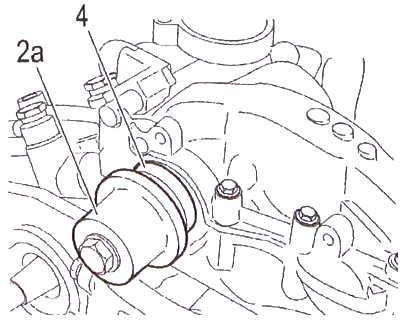
Install the seal using the tool.
Install the rest of the parts in reverse order.