



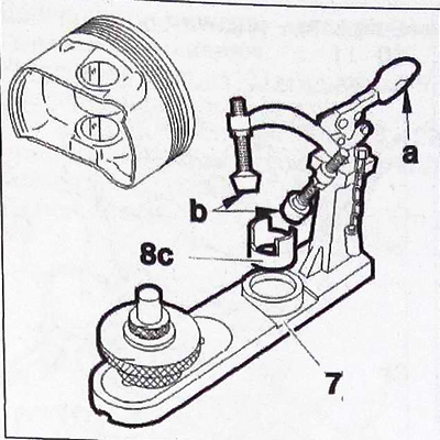
Unscrew the pushers (b) as much as possible.
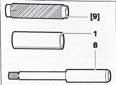
Install the pin (1) of the first piston into the guide mandrel 8.
Screw in handle 9 by hand without applying much force (until it stops).
 |
 |
Position the piston correctly in tool 8c so that the arrow and the "Dist" marking point upwards.
Insert the piston into the device 8 and guide it together with the assembled unit: handle, axle and guide tip.
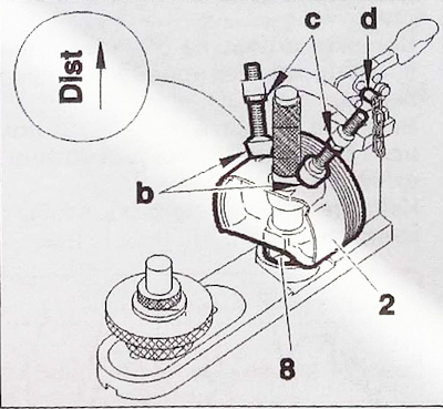
Insert the rod (d).
Screw in the pushers (b) until they touch the piston.
Tighten the nuts in area (c).
Remove the rod (d).
Secure the piston (2) in the bracket.
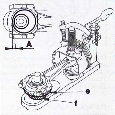
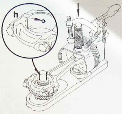
Insert the connecting rod together with its cap into the piston (without insert) and center it using the handle/piston pin/tip tool. Adjust the height of the stop (e) to bring it into contact with the connecting rod. Adjust the position of the stop (f) to obtain a clearance in zone A equal to 0.1 mm.
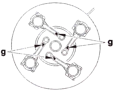
Place the connecting rods on an electric heater. Place a pinch of tin powder (g) into each connecting rod head. Heat until the tin melts to approximately 250°C.
Note: Lubricate the piston pins with engine oil.
Insert the connecting rod into the piston, correctly centering the grease hole (h).
Attention: It is very important to perform the following operations as quickly as possible.
Insert the piston pin (1) until it stops.
Wait a few seconds before removing the connecting rod/piston assembly.
Remove the drop of tin.
Proceed similarly for the remaining three nodes.
Note: To select bottom liners and side pads, please refer to the corresponding specification tables.
Install the main journal bearing shells with grooves (5) from the cylinder block side (6).
Lubricate the bearings with engine oil.
Install the crankshaft (3).
Install the side gaskets (4) by wrapping them around the crankshaft (the side with the groove is on the crankshaft side).
