



54. Drain the fluid from the cooling system.
55. Loosen, without removing, the central bolt and nut of the lower engine mount rubber.
56. Remove the air cleaner with tubes and channels and disconnect the crankcase ventilation tubes.
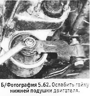
57. Unscrew the nut securing the rubber seal of the right engine mount.
58. Carefully raise the engine 6-8 mm using a lift or a reliable jack. Remove the 2 bolts securing the right engine support bracket to the cylinder head and lower the engine back into place.
59. Disconnect the fuel, water and vacuum lines from the cylinder head, carburetor and manifold, noting their position or marking them so as not to mix them up when connecting. Disconnect the throttle cable and wiring.
60. Disconnect the exhaust system downpipes from the exhaust manifold flange.
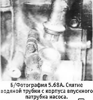
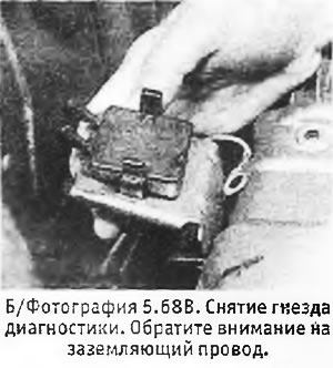
61. Remove the water tube from the pump inlet housing. Pull the diagnostic socket out of its bracket and unscrew the bolt securing the oil filler pipe to the intake manifold (see photos).
62. Remove the valve cover and distributor cap with high-voltage wires.
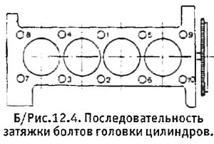
63. Loosen the cylinder head bolts in the reverse order of their tightening (see B/Figure 12.4). Remove the bolts.
64. Remove the cylinder head, loosening it if necessary using two rods inserted into the holes for the head bolts. Remove the head gasket and any loose pins. Be careful not to turn the crankshaft, as this will cause the cylinder liner seals to become dislodged, requiring the engine to be removed to reinstall the seals.
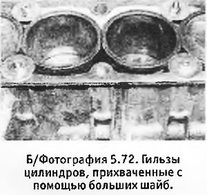
65. Secure the sleeves in place with clamps or large washers secured with nuts and bolts (see photo). If the liners become displaced, the engine will have to be removed to install new seals.
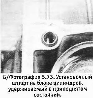
66. Begin installing the cylinder head by installing the guide pins on the block. Pry up the pin on the flywheel side by inserting a 5mm diameter punch or a large nail into the hole on the front surface of the block (see photo). Remove the clamps securing the sleeves.
67. Install a new cylinder head gasket (dry) with the protrusion towards the flywheel. Lower the head into place, making sure it fits onto the mounting pins. Pull out the punch (or a nail), support pin in raised position.
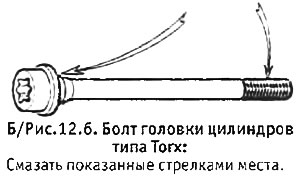
68. Insert the cylinder head bolts, after cleaning and lightly lubricating their threads with oil. Be sure to place a washer under the bolt located above the water pump.
 |
 |
69. Gradually tighten the bolts in the sequence shown in B/Figure 12.4 until the torque specified in Specifications for stage 1.
70. Raise the engine slightly and install the 2 bolts securing the right engine support bracket to the cylinder head. Tighten these bolts and loosen the bolt that secures the same bracket to the cylinder block. Lower the engine and tighten the right mount retaining nut and the lower mount rubber nut and bolt.
71. Loosen cylinder head bolt No. 1 and immediately tighten it to the torque specified in the Specifications for step 2. Tighten this bolt to the angle specified in Specifications for step 3. Repeat these operations for the remaining bolts, working in the sequence in which they were tightened.
72. Check and adjust valve clearances if necessary.
73. Install the remaining parts in the reverse order of their removal.
[Original is contained on the portal: PeugeotBook.ru]
74. Fill the system with coolant and bleed it.
75. Start the engine, warm it up to operating temperature, at which point the cooling fan turns on, then turn off the engine and let it cool for at least 2 hours.
76. Retighten the cylinder head bolts as described in paragraph 76 and recheck the valve clearances.
77. If a new camshaft drive belt is installed, re-tension it as specified in paragraph 42.
78. Tighten the engine support bracket bolt.